Silicon wafer boxing machine

A cartoning machine and silicon wafer technology, applied in packaging and other directions, can solve the problems of high personnel dependence, increased cartoning cost, low clamping and transportation efficiency, etc.

Pending Publication Date: 2020-02-28
HANGZHOU ZHONGWEI PHOTOELECTRICITY
View PDF0 Cites 3 Cited by
  • Summary
  • Abstract
  • Description
  • Claims
  • Application Information

AI Technical Summary

Problems solved by technology

[0002] Since the silicon wafers are fragile, in order to avoid damage during transportation, the silicon wafers are packed in foam boxes, each box of silicon wafers is separated by foam, and a piece of corrugated cardboard is placed on the outermost layer, so that the silicon wafers The film is relatively static in the foam box, and there is foam cushioning protection during transportation to avoid collision damage. Because this "sandwich" boxing method is cumbersome, the traditional boxing method is still manual. During the boxing process, the efficiency of clamping and transportation is not high, and the dependence on personnel is high, which increases the cost of boxing

Method used


Image

  • Silicon wafer boxing machine
  • Silicon wafer boxing machine
  • Silicon wafer boxing machine

Examples


Embodiment 1

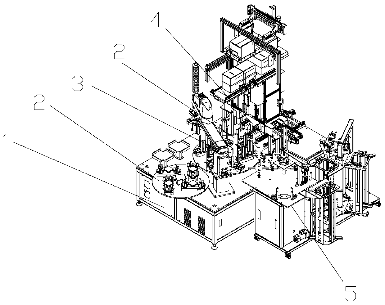
[0051] Such as figure 1 A silicon wafer cartoning machine shown includes a main frame 1, a turntable 2, a mechanical gripper 3, a box loading mechanism 4, and an interlayer configuration mechanism 5. The interlayer configuration mechanism 5 is arranged on one side of the main frame 1, and two turntables 2 are installed side by side on the table of the main frame 1, the mechanical gripper 3 is installed between the two turntables 2 and the interlayer arrangement mechanism 5, and the box loading mechanism 4 is installed on one side of the turntable 2. The quality of the silicon wafers is firstly distinguished by an external device, and the silicon wafers with different degrees of quality are distinguished and placed in the place, and then the interlayer configured on the interlayer configuration mechanism 5 is grabbed by the mechanical gripper, and the silicon wafer and the interlayer are placed together. On the other turntable 2, finally, the box loading mechanism 4 picks up th...

Embodiment 2

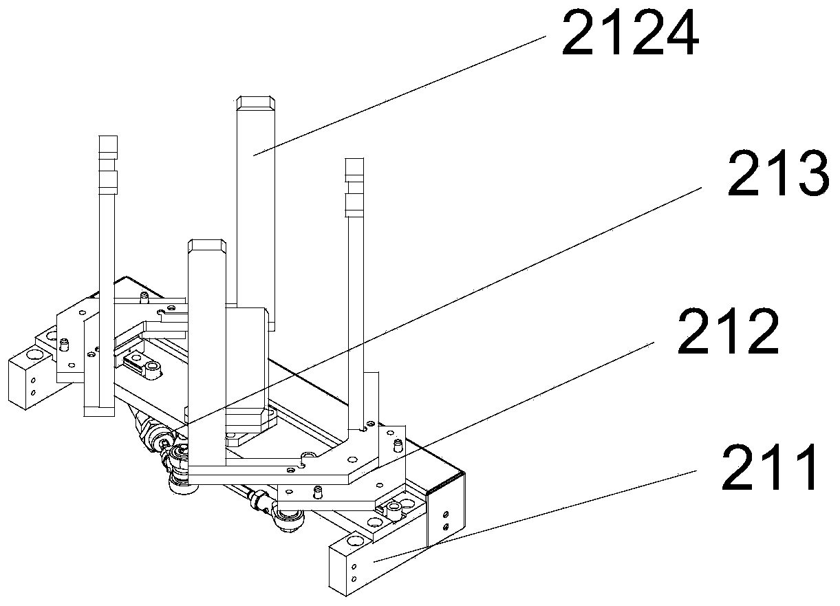
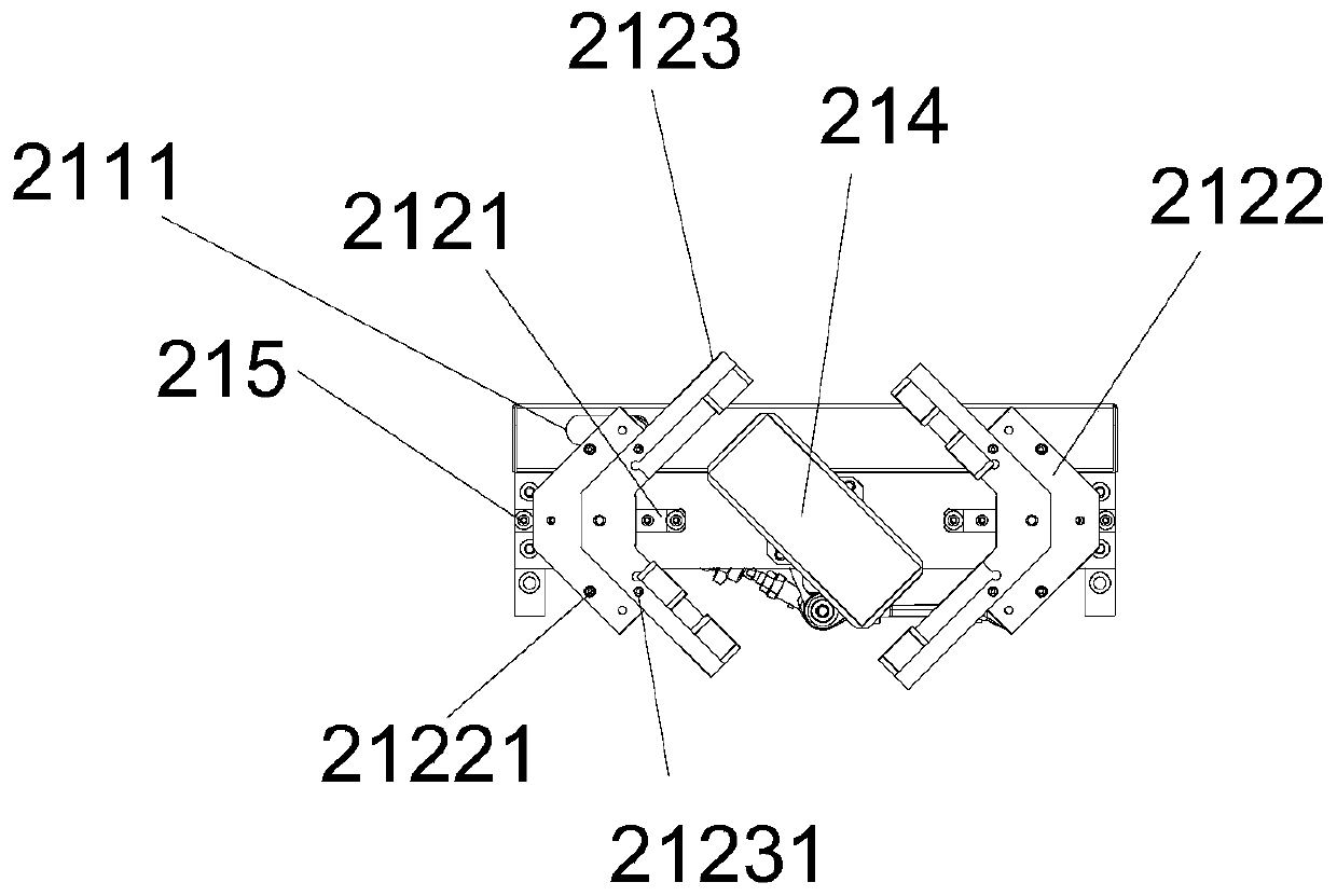
[0060] A silicon wafer cartoning machine as shown in Embodiment 1, the only difference is that the clamping module 212 includes a linear slide rail 1 2121, a slider connecting plate 2122, a backing plate mounting plate 2123, a backing plate 2124, and a linear slide rail One 2121 is fixed on both ends of the installation plate one 211, and each linear slide rail one 2121 is slidably provided with a slider connecting plate 2122, and the leaning plate mounting plate 2123 is clamped on the slider connecting plate 2122, and the leaning plate 2124 is fixed On the board mounting plate 2123.

[0061] Such as figure 2 , image 3 , Figure 4 As shown, the driving module 213 includes a driving cylinder 1 2131, a rotating plate 2132, a connecting rod 2133, and a connecting rod 2 2134. The driving cylinder 1 2131 is fixed on the mounting plate 1 211, and the rotating plate 2132 is rotatably mounted on the mounting plate 1 211. One end of the rotating plate 2132 is connected to the driv...

Embodiment 3

[0068] A kind of silicon cartoning machine shown in embodiment 1, its difference is only, as Figure 9 , Figure 10 , Figure 11 As shown, the silicon wafer tightening module 41 includes a tightening fixture 411, a driving motor 41212, a coupling 413, a tightening screw 414, a tightening nut 415, and a pressing plate structure 416. The driving motor 41212 is installed on the tightening fixture 411 One end of the coupling 413 is connected to the output end of the driving motor 41212, and the other end of the coupling 413 is connected to the tightening screw 414, and the tightening screw 414 is equipped with two tightening nuts 415 that turn in opposite directions, each tightening A pressing plate structure 416 is slidably disposed on the tight nut 415 .

[0069]The tightening nut 415 is driven to move up and down by the rotation of the drive motor 412 , thereby realizing the up and down movement of the pressing plate structure 416 . Tightening the fixed frame 411 also includ...


PUM


Abstract

The invention discloses a silicon wafer boxing machine which comprises a main frame platform, turntables, a mechanical gripper, a boxing mechanism and an interlayer configuration mechanism. The interlayer configuration mechanism is arranged on one side of the main frame platform and used for configuring interlayers of various types; the two turntables are arranged on the platform surface of the main machine platform side by side, and the turntables are used for screening silicon wafers with different qualities; the mechanical gripper is installed between the two turntables and the interlayer configuration mechanism, and can be used for grabbing the silicon wafers and the silicon wafer interlayers to realize layering of the silicon wafers; and the boxing mechanism is arranged on one side ofthe turntables, and can automatically finish clamping and sorting of the layered silicon wafers to finally realize boxing. The silicon wafer boxing machine is high in silicon wafer sorting and classifying efficiency and low in personnel dependence, and has the advantages of good integrity of clamped silicon wafers and wide application.

Description

technical field [0001] The invention relates to silicon wafer boxing equipment, in particular to a silicon wafer boxing machine. Background technique [0002] Since the silicon wafers are fragile, in order to avoid damage during transportation, the silicon wafers are packed in foam boxes, each box of silicon wafers is separated by foam, and a piece of corrugated cardboard is placed on the outermost layer, so that the silicon wafers The film is relatively static in the foam box, and there is foam cushioning protection during transportation to avoid collision damage. Because this "sandwich" boxing method is cumbersome, the traditional boxing method is still manual. In the process of boxing, the efficiency of clamping and transportation is not high, and the dependence on personnel is high, which increases the cost of boxing. Contents of the invention [0003] The technical problem to be solved by the present invention is to provide a silicon wafer cartoning machine in view o...

Claims


Application Information

Patent Timeline
IPC IPC(8): B65B35/16
CPCB65B35/16Y02P70/50
Inventor 叶欣胡普查张广犬孙培文王俊王亚伟黄游谢可馨
Owner HANGZHOU ZHONGWEI PHOTOELECTRICITY
Why Eureka
Try Eureka