Supercharge Your Innovation With Domain-Expert AI Agents!

Comb-shaped limit damper suitable for bridge structure

A bridge structure and damper technology, applied in the direction of bridges, bridge parts, bridge construction, etc., can solve the problems of no energy consumption, longitudinal falling beams, weakened abutment restraint, etc., to reduce impact force, facilitate construction, low cost effect

Active Publication Date: 2020-02-28
XI'AN UNIVERSITY OF ARCHITECTURE AND TECHNOLOGY
View PDF6 Cites 0 Cited by
  • Summary
  • Abstract
  • Description
  • Claims
  • Application Information

AI Technical Summary

Problems solved by technology

However, it should be noted that the limiting effect of the abutment is effective for small bridges. For large and medium-sized bridges, due to the large number of expansion joints, the longitudinal limiting effect of the abutment is greatly reduced. If the back wall of the abutment is damaged, the The restraining effect of the abutment is greatly weakened, resulting in falling beams. There is still a lot of room for improvement in the existing seismic technology and structural measures
[0003] At present, in bridge structures, transverse concrete blocks are usually installed at both ends of the main girder, but in non-strong earthquake areas, longitudinal blocks are often not set, and longitudinal beams are prone to fall under the action of earthquakes
The usual method of longitudinal restraint in strong earthquake areas is to install cables between pier beams. Although it can reduce the occurrence of earthquake damage from falling beams to a certain extent, it basically has no energy consumption effect and has a relatively single function.

Method used


Image

  • Comb-shaped limit damper suitable for bridge structure
  • Comb-shaped limit damper suitable for bridge structure
  • Comb-shaped limit damper suitable for bridge structure

Examples


Embodiment Construction

[0025] The present invention is described in further detail below in conjunction with accompanying drawing:

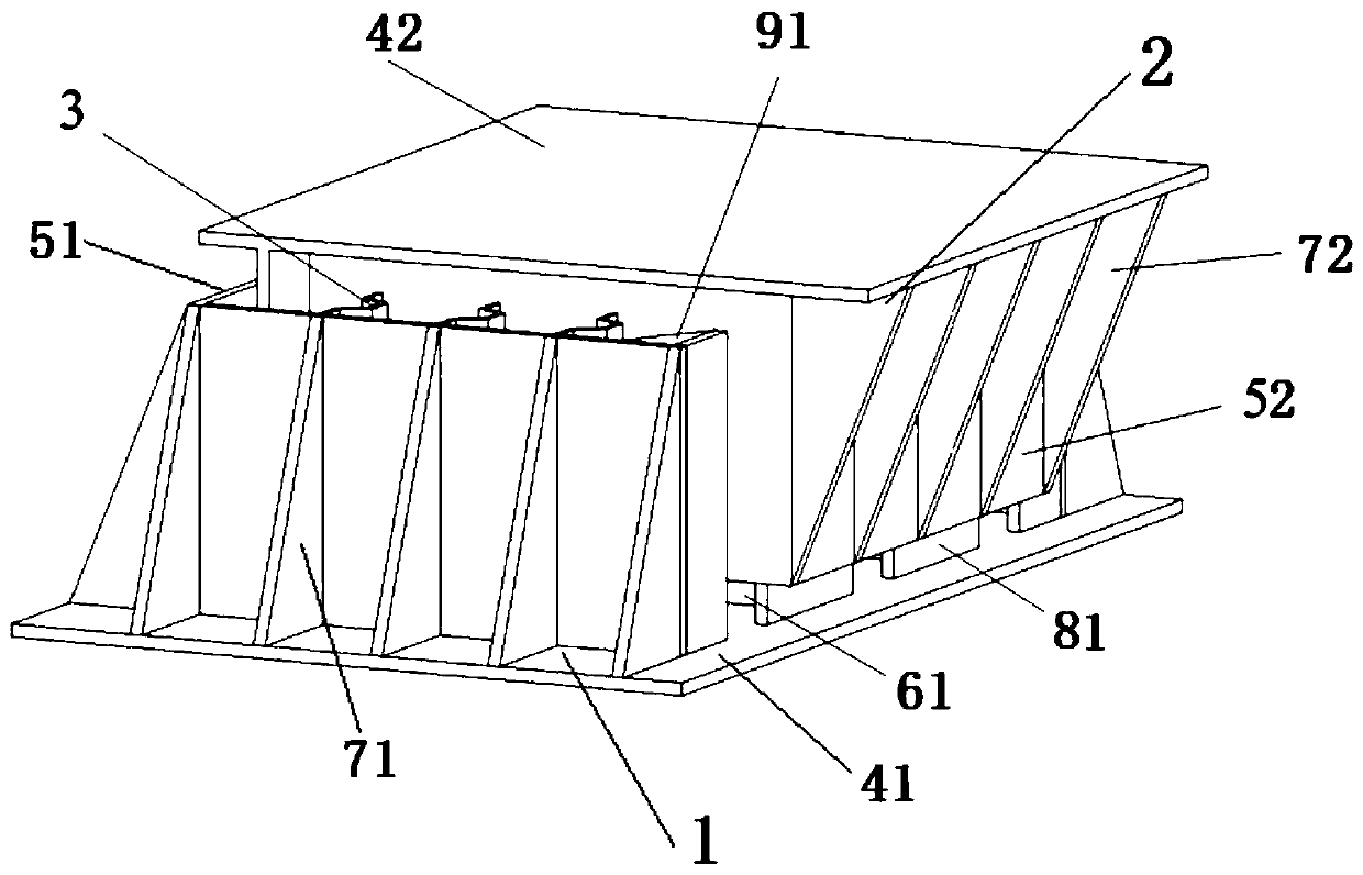
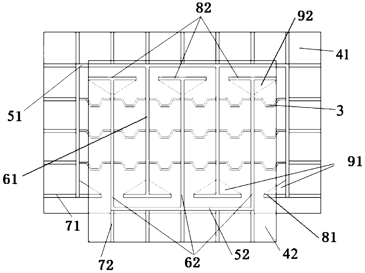
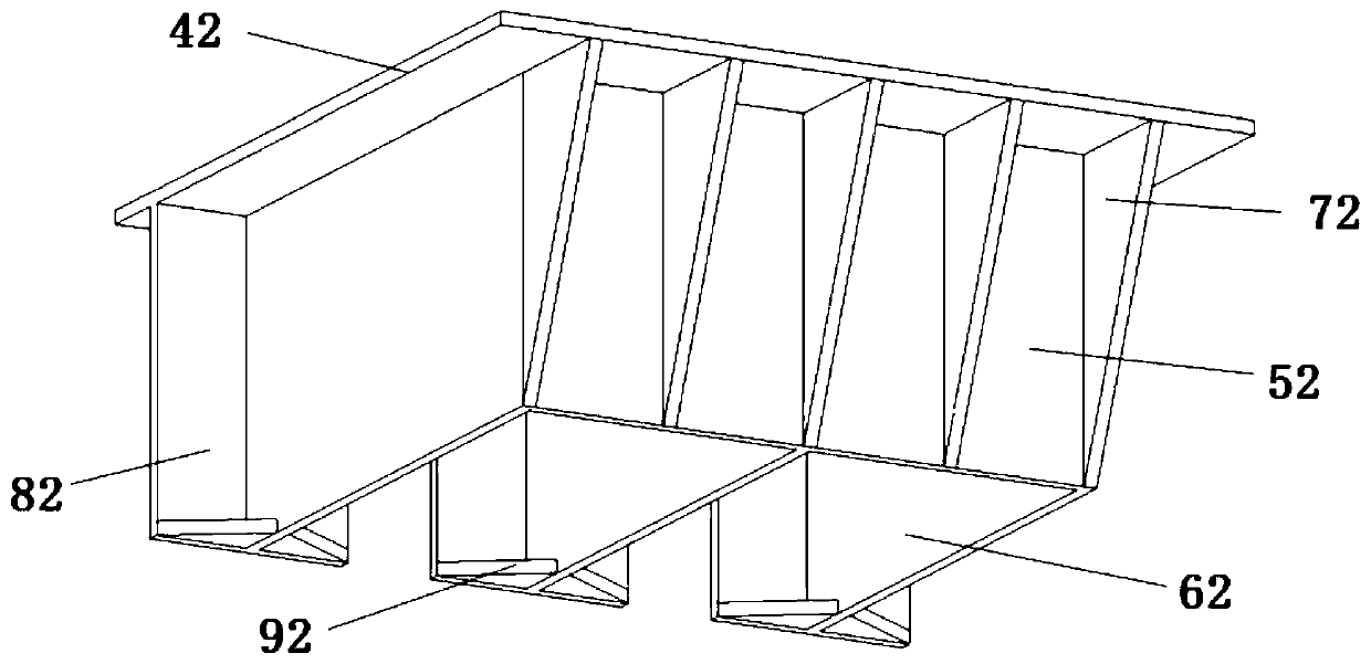
[0026] refer to Figure 1 to Figure 5 The comb-tooth-shaped limit damper suitable for bridge structures according to the present invention includes a damper superstructure 1 and a damper substructure 2, and the damper superstructure 1 includes a first side end plate 51, a bottom end plate 41 and several The first comb tooth plate 61; the damper lower structure 2 includes the second side end plate 52, the top end plate 42 and a plurality of second comb tooth plates 62; the first side end plate 51 is fixed on the bottom end plate 41, each first comb The bottom of the tooth plate 61 is fixed on the bottom end plate 41, one end of each first comb tooth plate 61 is all fixed on the first side end plate 51, the second side end plate 52 is fixed on the bottom of the top end plate 42, each second The top of the comb tooth plate 62 is fixed on the bottom of the top plate 42, a...


PUM


Abstract

The invention discloses a comb-shaped limit damper suitable for a bridge structure. A first side end plate is fixed to a bottom end plate, the bottom of each first comb plate is fixed to the bottom end plate, one end of each first comb plate is fixed to the first side end plate, a second side end plate is fixed to the bottom of a top end plate, the top of each second comb plate is fixed to the bottom of the top end plate, and one end of each second comb plate is fixed to the second side end plate; each first comb plate and each second comb plate are sequentially distributed in a staggered mode, first limit end plates are correspondingly fixed to the other end of each first comb plate, second limit end plates are correspondingly fixed to the other end of each second comb plate, each secondlimit end plate is located between the adjacent first comb plates, and each first limit end plate is located between the adjacent second comb plates; and the side surface of the adjacent first comb plate is connected with the side surface of the adjacent second comb plate by wave-shaped energy-consuming soft steel. According to the damper, the two-way limit in the directions of along bridge and cross bridge of a bridge can be achieved, and meanwhile the function of energy consumption is achieved.

Description

technical field [0001] The invention belongs to the technical field of bridges and relates to a comb-tooth-shaped limit damper suitable for bridge structures. Background technique [0002] Continuous girder bridges are generally equipped with multiple expansion joints, which provide space for the displacement of the main girder under earthquake action, and the risk of girder falling is relatively high. During an earthquake, the girder, pier, support, abutment, bridge deck continuity, main girder transverse connection system, and pier-abutment block of a girder bridge constitute a complete seismic system, and the support has weak constraints on the displacement of the main girder. The bridge deck pavement coordinates the displacement of the main girder in a joint, and plays the role of the connecting girder device. The abutment effectively restrains the longitudinal displacement of the main girder, and the stopper effectively restrains the lateral displacement of the main gir...

Claims


Application Information

Patent Timeline
Patent Type & Authority Applications(China)
IPC IPC(8): E01D19/00E04B1/98E04H9/02
CPCE01D19/00E04B1/98E04H9/021
Inventor 王威李昱徐金兰权超超黄元昭甄国凯
Owner XI'AN UNIVERSITY OF ARCHITECTURE AND TECHNOLOGY
Features
  • R&D
  • Intellectual Property
  • Life Sciences
  • Materials
  • Tech Scout
  • Unparalleled Data Quality
  • Higher Quality Content
  • 60% Fewer Hallucinations
Learn More