A control device for a fan oscillating head assembly, a control method thereof, and a fan

A fan head shaking and control device technology, which is applied in pump control, pump devices, non-variable pumps, etc., can solve the problems of fan motor damage, affecting user experience, fan motor stalling, etc., to reduce the time of stalling, The effect of improving user experience satisfaction

Active Publication Date: 2020-12-22
珠海艾维普信息技术有限公司 +1
View PDF4 Cites 0 Cited by
  • Summary
  • Abstract
  • Description
  • Claims
  • Application Information

AI Technical Summary

Problems solved by technology

[0003] When the fan shakes the head and the fan shakes the head assembly to rotate from the current position to the specified position, the conventional determination of the current position of the fan shakes the head assembly and the determination of the set position only depends on the light baffle set in the fan shakes the head assembly, resulting in the fan shakes the head assembly In the process of rotating to the specified position, in addition to rotating at a large angle and taking a long time, which affects the user experience, the fan motor may also be blocked, causing certain damage to the fan motor

Method used


Image

  • A control device for a fan oscillating head assembly, a control method thereof, and a fan
  • A control device for a fan oscillating head assembly, a control method thereof, and a fan
  • A control device for a fan oscillating head assembly, a control method thereof, and a fan

Examples


Embodiment Construction

[0030] The present invention will be further described in detail below in conjunction with the accompanying drawings and embodiments. It should be understood that the specific embodiments described here are only used to explain the present invention, but not to limit the present invention. In addition, it should be noted that, for the convenience of description, only some structures related to the present invention are shown in the drawings but not all structures.

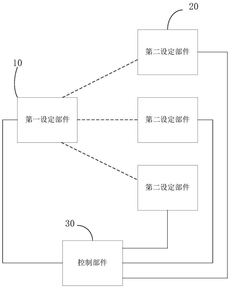
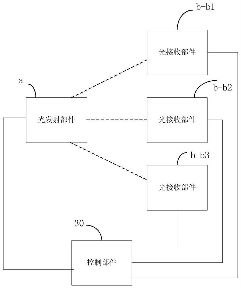
[0031] figure 1 It is a schematic structural diagram of the control device of the first fan oscillating head assembly provided by the embodiment of the present invention, as shown in figure 1 As shown, the control device of the fan oscillating head assembly includes a first setting part 10 and a plurality of second setting parts 20, the first setting part 10 is a light emitting part and the second setting part 20 is a light receiving part, Or the first setting part 10 is a light receiving part and the second sett...


PUM


Abstract

An embodiment of the invention discloses a control device and method of a fan head shaking assembly and a fan. According to the control device, a first setting part and multiple second setting parts are arranged, the first setting part serves as a light emission part and the second setting parts serve as light reception parts, or the first setting part serves as a light reception part and the second setting parts serve as light emission parts. When the light reception parts receive light emitted by the light emission part, a light detection signal is generated. A control part determines the position of the fan head shaking assembly according to the received light detection signal and controls the fan head shaking assembly to rotate to the set position along the shortest path according to the position. By means of the technical scheme, the purpose that the fan head shaking assembly is quickly rotated to the set position from the position where the fan head shaking assembly is located when the fan is started or closed is achieved, the degree of satisfaction of the user experience is improved, the motor stalling time of the fan is shortened, and a fan motor is protected.

Description

technical field [0001] The embodiments of the present invention relate to the technical field of fans, and in particular, to a control device for a fan oscillating head assembly, a control method thereof, and a fan. Background technique [0002] At present, the fan can provide multi-level air supply mode. In order to realize that the fan can deliver air in different directions, the fan has the function of shaking the head. [0003] When the fan shakes the head and the fan shakes the head assembly to rotate from the current position to the specified position, the conventional determination of the current position of the fan shakes the head assembly and the determination of the set position only depends on the light baffle set in the fan shakes the head assembly, resulting in the fan shakes the head assembly In the process of rotating to the specified position, in addition to the possibility of rotating at a large angle and taking a long time, which affects the user experience...

Claims


Application Information

Patent Timeline
Patent Type & Authority Patents(China)
IPC IPC(8): F04D25/10F04D27/00
CPCF04D25/105F04D27/00
Inventor 刘江
Owner 珠海艾维普信息技术有限公司
Why Eureka
Try Eureka