
Power-on and power-off remote control system and method for power supply

A remote control system and power supply technology, which is applied in the field of communication, can solve the problems of power failure and low cost of the first-level power supply module, and achieve the effects of saving PCB space, saving cost and simplifying design

Pending Publication Date: 2020-02-28
北京浩瀚深度信息技术股份有限公司
View PDF0 Cites 2 Cited by
  • Summary
  • Abstract
  • Description
  • Claims
  • Application Information

AI Technical Summary

Problems solved by technology

If you want to realize unmanned remote operation, in the ATCA standard (AdvancedTCA), it is realized by relying on the chassis management topology, but this method has the following disadvantages: 1. It is necessary to set up an independent power monitoring module, which requires design At the beginning, this module was considered in the system design, providing an independent power supply circuit and reserved PCB area; 2. This module must be a relatively complex control chip plus some external interface chips to maintain the interface Communication, and analyze the commands sent by the control board; the cost of such a module is not low; 3. This module needs an independent communication channel to communicate with the control platform. In the ATCA architecture, it is an IPMB channel, and Ethernet is commonly used in other systems. That is, it is necessary to add another network cable and an IP address; 4. Only the main business functions of the service board are powered off, and there is a first-level power module and the monitoring module itself that cannot be powered off

Method used


Image

  • Power-on and power-off remote control system and method for power supply
  • Power-on and power-off remote control system and method for power supply
  • Power-on and power-off remote control system and method for power supply

Examples


Embodiment Construction

[0030] In order to better understand the present invention, the present invention will be further described below in conjunction with specific embodiments and accompanying drawings.

[0031] In the communication field, after a service board works normally on the live network, some faults may occur from time to time. The solution for the maintenance personnel is usually to power off the board and then power it on again. In the prior art, in order to realize unmanned remote operation, in the ATCA standard (Advanced Telecom Computing Architecture), it is realized by means of chassis management topology.

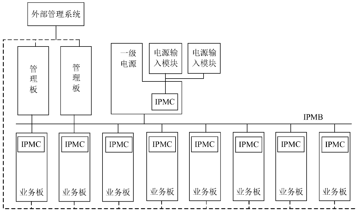
[0032] Such as figure 1 As shown, in this technical solution, a plurality of independent service boards are arranged in the chassis, and an IPMC (Intelligent Power Module Controller) module is arranged in each service board, and the IPMC module is independent of other modules in the service version, and its It supplies power to other modules in each independent service board. T...


PUM


Abstract

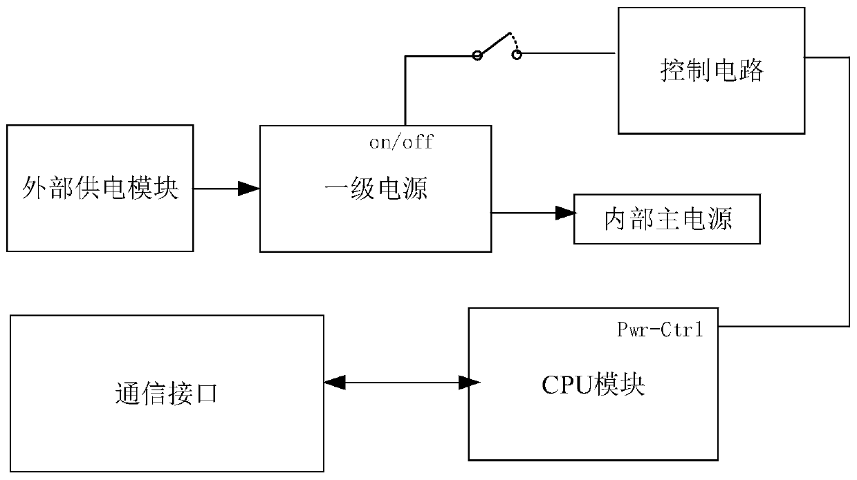
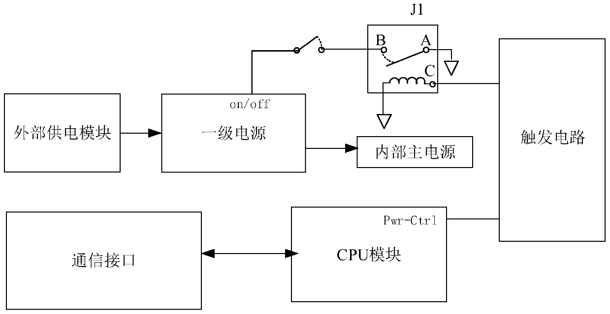
The invention provides a power-on and power-off remote control system and method for a power supply, and the system comprises a communication board card; the communication board card at least comprises a CPU module and a power supply module; the CPU module at least comprises a communication interface, and the communication interface realizes the communication with an external network; the power supply module comprises a primary power supply and an internal main power supply connected with the primary power supply, and the primary power supply is externally connected with an external power supply module; a control circuit is arranged between the primary power supply and the CPU module; the CPU module receives a power-off instruction through the communication interface, and achieves the switching control of the primary power supply through the control circuit. According to the invention, a complex chip does not need to be used as an independent module, a special power supply circuit is not needed, and only the control circuit with extremely low cost is needed, so the design is simplified, the cost is saved, and the tense PCB space is saved.

Description

technical field [0001] The invention relates to the field of communications, in particular to a remote control system and method for powering on and off a power supply. Background technique [0002] In the communication field, after a service board works normally on the live network, some failures may occur from time to time. The solution for maintenance personnel is to power off and then power on the board. To achieve this operation, one way is to ask the maintenance personnel to go to the site and press the switch to power off the board and then power it on again, but this kind of labor cost is too high. If you want to realize unmanned remote operation, in the ATCA standard (AdvancedTCA), it is realized by relying on the chassis management topology, but this method has the following disadvantages: 1. It is necessary to set up an independent power monitoring module, which requires At the beginning, this module was considered in the system design, providing it with an indep...

Claims


Application Information

Patent Timeline
IPC IPC(8): G05B19/042H04L12/12
CPCG05B19/042H04L12/12Y02D30/50
Inventor 黄少杰魏强吴晓春安丰军
Owner 北京浩瀚深度信息技术股份有限公司
Learn More