Time headway-based road vehicle lane change model calibration method, time headway-based road vehicle lane change decision making method and device

A technology of headway distance and calibration method, applied in the field of traffic flow, can solve the problems of complex structure of lane changing model, difficult to solve, difficult to meet research needs, etc., achieving good simulation effect, low complexity, and convenient simulation research and application. Effect

Active Publication Date: 2020-02-28
SOUTHEAST UNIV
View PDF5 Cites 14 Cited by
  • Summary
  • Abstract
  • Description
  • Claims
  • Application Information

AI Technical Summary

Problems solved by technology

Most of the traditional lane change models are complex in structure and difficult to solve, requiring a large amount of data for model calibration, which is difficult to meet the current research needs

Method used


Image

  • Time headway-based road vehicle lane change model calibration method, time headway-based road vehicle lane change decision making method and device
  • Time headway-based road vehicle lane change model calibration method, time headway-based road vehicle lane change decision making method and device
  • Time headway-based road vehicle lane change model calibration method, time headway-based road vehicle lane change decision making method and device

Examples


Embodiment 1

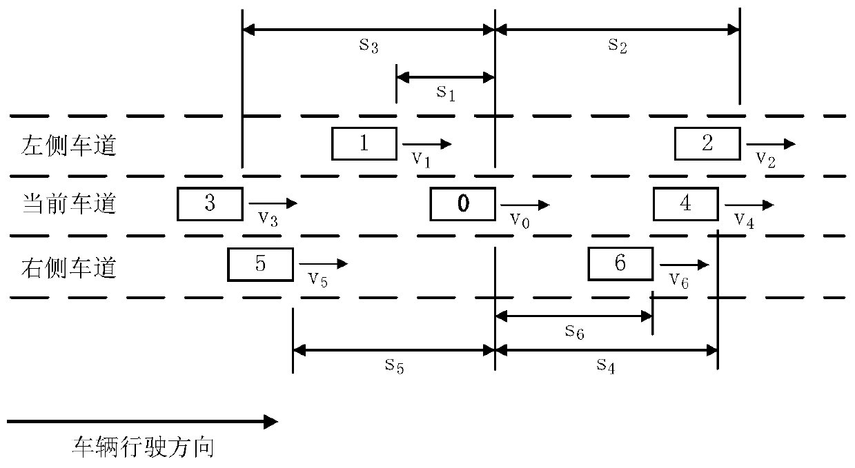
[0034] Example 1: If the observation area is an ordinary road section, such as figure 2 As shown, the vehicle is driving to the right, and car 0 is the target vehicle. Car 4 and Car 3 are the front car and rear car in the current lane respectively; Car 2 and Car 1 are the front car and rear car in the left lane respectively; Car 6 and Car 5 are the front car and rear car in the right lane. Then the measured data includes the target vehicle speed v 0 , the surrounding vehicle speed v i (i=1, 2, 3, 4, 5, 6), the headway distance s between the target vehicle and surrounding vehicles i (i=1, 2, 3, 4, 5, 6).

Embodiment 2

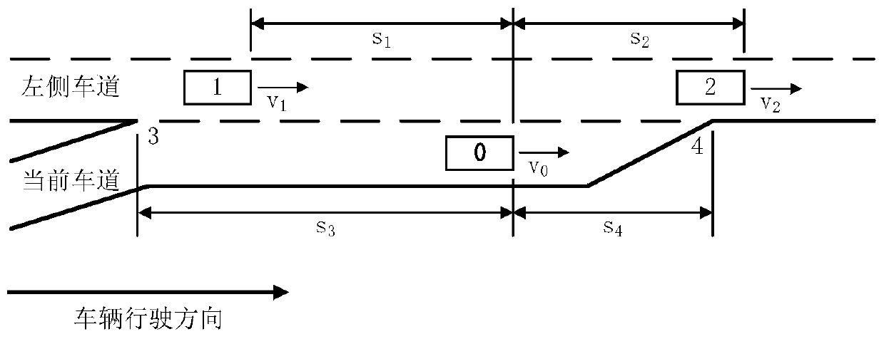
[0035] Example 2: If the observation area is the entrance ramp area, such as image 3 As shown, vehicle 0 is the target vehicle. If there is no vehicle in front of the current lane, the end point of the on-ramp (the vehicle must complete the lane change before this position) is taken as the static obstacle in front, which is recorded as point 4; Road) as the rear static obstacle, recorded as point 3; car 2 and car 1 are the front car and rear car in the left lane respectively; there is no right lane. Then the measured data includes the target vehicle speed v 0 , the speed of surrounding vehicles or obstacles v i (i=1, 2, 3, 4), the headway distance s between the target vehicle and surrounding vehicles or obstacles i (i=1, 2, 3, 4).

Embodiment 3

[0036] Example 3: If the observation area is the off-ramp area, such as Figure 4As shown, vehicle 0 is the target vehicle. Car 4 and Car 3 are the front car and the rear car in the current lane respectively; Car 2 and Car 1 are the front car and the rear car in the left lane respectively; there is no car in front of the right lane, and the end of the exit ramp is taken as the static obstacle ahead, which is recorded as Point 4: There is no car behind the right lane, and the starting point of the exit ramp is taken as the rear static obstacle, which is recorded as point 3. Then the measured data includes the target vehicle speed v 0 , the speed of surrounding vehicles or obstacles v i (i=1, 2, 3, 4, 5, 6), the headway distance s between the target vehicle and surrounding vehicles or obstacles i (i=1, 2, 3, 4, 5, 6).


PUM


Abstract

The invention discloses a time headway-based road vehicle change model calibration method, a time headway-based road vehicle lane change decision making method and a device. The vehicle lane change model calibration method comprises the steps of obtaining measured data of a vehicle and a road, wherein the measured data comprises the fact whether the lane of the vehicle has adjacent lanes or not, distances between the vehicle and vehicles in the front and rear on the same lane and the adjacent lanes and speeds of related vehicles; determining a lane change direction and determining whether a lane change motive exists or not and a target lane according to a time headway; constructing a time headway-based logistic vehicle lane change model; and extracting condition data indicating lane changesuccess and lane change rejection of a target vehicle so as to calibrate the vehicle lane change model. The time headway-based road vehicle change model calibration method is low in complexity, strong in applicability, less in data quantity demand, high in calculation efficiency and good in simulation effect, is capable of obtaining reliable vehicle lane change models through less measured data of vehicles and roads to simulate vehicle lane change behaviors, thereby researching the vehicle lane change behaviors, predicting the traffic flow states and providing help to ease the traffic congestion, decrease the hidden trouble of traffic and reduce the resource waste.

Description

technical field [0001] The invention relates to a road vehicle lane-changing decision-making technology based on headway, and belongs to the technical field of traffic flow. The invention realizes the lane-changing decision simulation of highway vehicles by constructing a logistic vehicle lane-changing model based on headway. Background technique [0002] Vehicle lane changing behavior is an important research content in the field of traffic flow, and it is an important basis for analyzing driving behavior, predicting traffic flow status, alleviating traffic congestion, and reducing traffic hazards. In order to avoid the influence of various control measures on the vehicle behavior in urban roads, road vehicles are generally taken as the research object. Limited by the cost and conditions of field experiments and observations, it has become the main research method in this field to measure a small amount of vehicle and road data to construct and calibrate the lane-changing ...

Claims


Application Information

Patent Timeline
Patent Type & Authority Applications(China)
IPC IPC(8): G08G1/07
CPCG08G1/07
Inventor 王昊陈全
Owner SOUTHEAST UNIV
Why Eureka
Try Eureka