Vacuum load switch

A vacuum load and switch technology, applied in the direction of electric switches, high-voltage/high-current switches, high-voltage air circuit breakers, etc., can solve problems such as laborious installation, reduce production costs, and micro-deformation, and achieve control accuracy and stability. The structural design is simple and reasonable, and the effect of improving work safety

Active Publication Date: 2020-02-28
ZHEJIANG ZIGUANG ELECTRIC APPLIANCE
View PDF5 Cites 0 Cited by
  • Summary
  • Abstract
  • Description
  • Claims
  • Application Information

AI Technical Summary

Problems solved by technology

However, this technical solution has the following disadvantages: when the switch is switched on and energized, the crank arms in the four-bar linkage mechanism and the energy storage mechanism are subject to continuous pressure, and are prone to slight deformation, especially at the hinge points at both ends of

Method used


Image

  • Vacuum load switch
  • Vacuum load switch
  • Vacuum load switch

Examples


Example Embodiment

[0025] The following are specific embodiments of the present invention and the accompanying drawings to further describe the technical solutions of the present invention, but the present invention is not limited to these embodiments.

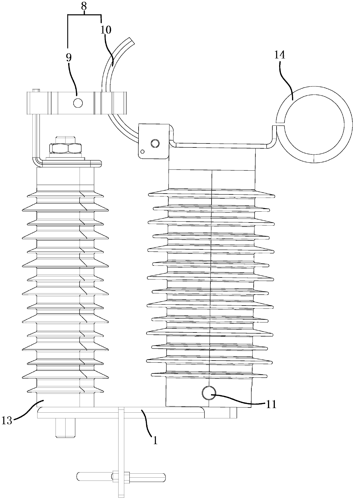
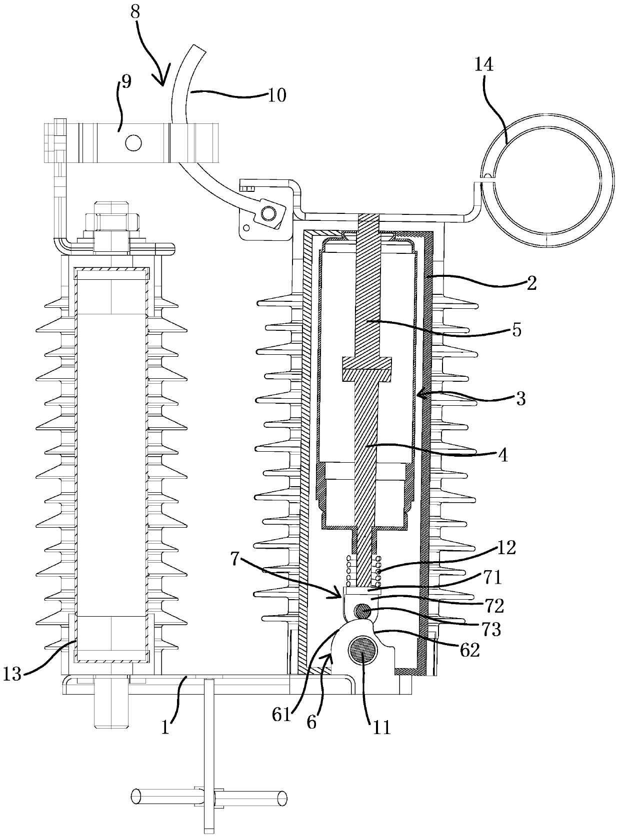
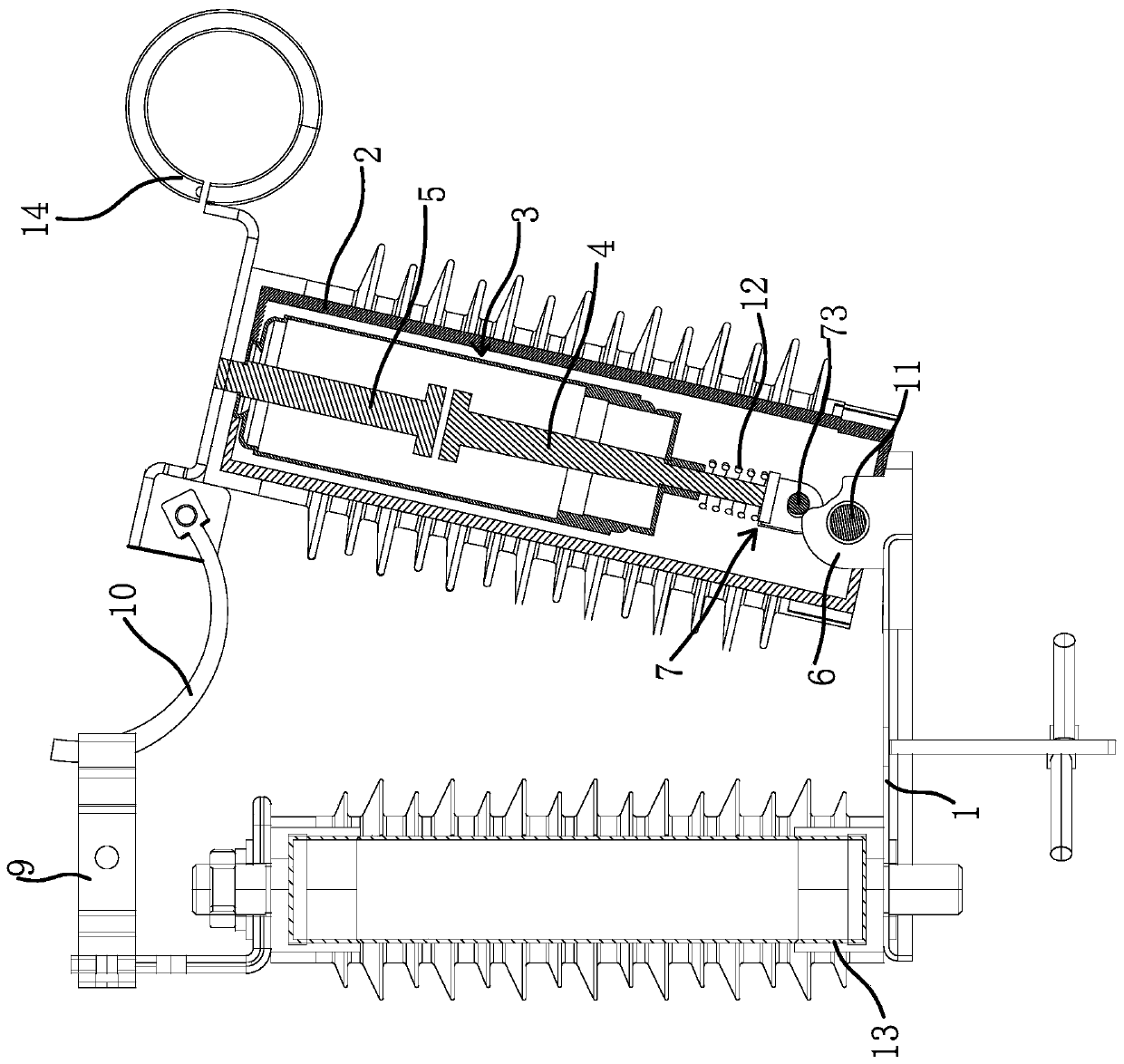
[0026] like figure 1 and figure 2 As shown, this embodiment includes a base 1, a cylindrical shell 2 and a conductive column 13 arranged at opposite intervals, an insulating sleeve is sleeved on the shell 2 and the conductive column 13, and the lower end of the shell 2 is hinged with the base 1, It is convenient for the housing 2 to rotate on the base 1 . The housing 2 is provided with a vacuum interrupter 3, the vacuum interrupter 3 includes a vacuum chamber, and a static contact rod 5 and a movable contact rod 4 in contact with the static contact rod 5 are inserted into the vacuum chamber. Moving up and down along the vacuum chamber, the housing 2 is also provided with a return spring 12 that keeps the movable contact rod 4 away from the st...


PUM


Abstract

The invention provides a vacuum load switch, belongs to the technical field of a high-voltage switch and solves technical problems of poor operation stability and the like of a vacuum load switch in the prior art. The vacuum load switch comprises a base, a conductive column, a shell, a vacuum arc-extinguishing chamber, a static contact rod, a movable contact rod and a reset spring, wherein an upper end of the conductive column is connected with an upper end of the shell through a delay switch, a lower end of the shell is hinged with the base, the base is fixedly connected with a cam with a convex curved surface and a concave curved surface, a lower end of the movable contact rod abuts against the convex curved surface, the movable contact rod is contacted with the static contact rod and iscommunicated with a time delay switch, when the shell swings outwards to a first position relative to the conductive column, a lower end of the movable contact rod abuts against the concave curved surface, the movable contact rod is separated from the static contact rod, the time delay switch is kept in an on state, and when the shell continuously swings outwards to a second position relative tothe conductive column, the movable contact rod is separated from the static contact rod, and the time delay switch is switched off. The vacuum load switch is advantaged in that the vacuum load switchis simple and reasonable in structure, and operation stability of the vacuum load switch is improved.

Description

technical field [0001] The invention belongs to the technical field of high-voltage switches, in particular to a vacuum load switch. Background technique [0002] Vacuum load switch is an electrical appliance with functions between high-voltage circuit breakers and high-voltage isolation switches. It can switch on and off certain load current and overload current, and has been widely used in high-voltage power transmission and distribution. The vacuum load switch generally includes a cylindrical shell with a vacuum interrupter, a static contact rod whose lower end is inserted into the vacuum interrupter, a movable contact rod whose upper end is inserted into the vacuum interrupter and can move up and down along the vacuum interrupter, and The opening and closing device used to control the contact between the movable contact rod and the static contact rod of the vacuum interrupter. [0003] For example, Chinese patent literature (application number: 03280041.X) discloses a v...

Claims


Application Information

Patent Timeline
IPC IPC(8): H01H33/666H01H33/662
CPCH01H33/666H01H33/66207
Inventor 周鹤铭
Owner ZHEJIANG ZIGUANG ELECTRIC APPLIANCE
Why Eureka
Try Eureka