Automatic heat-dissipation and moisture-proof power distribution cabinet installation box

A technology for power distribution cabinets and installation boxes, which is applied to the substation/power distribution device shell, electrical components, substation/switch layout details, etc., and can solve the problems that the power distribution cabinet does not have heat dissipation and moisture resistance, and the power distribution cabinet is prone to failure, etc. , to achieve the effect of easy promotion, simple structure and moisture prevention

Active Publication Date: 2020-02-28
NAN TONG HUAWEI POWER EQUIP CO LTD
5 Cites 9 Cited by

AI-Extracted Technical Summary

Problems solved by technology

[0003] Power distribution cabinets for special occasions generally require moisture-proof, ventilation and heat dissipation treatment. If moisture-proof and heat dissipation are not carried out, the power distribution cabinet...

Abstract

The invention discloses an automatic heat-dissipation and moisture-proof power distribution cabinet installation box. A main box body is included. An installation cavity is arranged in the main box body. Two groups of sliding plates in a bilateral symmetry mode are arranged in the installation cavity in a sliding manner. Clamping plates are slidably arranged on side surfaces, close to each other,of the two groups of sliding plates. The clamping plates are used for clamping a power distribution cabinet. A fixed block is fixedly arranged on a bottom wall of the installation cavity. A row of rolling shafts are rotatably arranged on a top surface of the fixed block. In wetter weather or rainy days, sealed motor operation can be achieved so that a first sealing plate and a second sealing platemove at the same time; a side cavity and a top cavity are closed so that humid air cannot enter into the installation cavity and the power distribution cabinet is prevented from being affected with damp; and meanwhile, the power distribution cabinet can be conveniently put in and taken out for maintenance through a rolling shaft, the power distribution cabinet can be automatically clamped in themiddle portion of the installation cavity through the clamping plates, and the power distribution cabinet and a connector lug are conveniently connected with a power connection plate.

Application Domain

Technology Topic

Image

  • Automatic heat-dissipation and moisture-proof power distribution cabinet installation box
  • Automatic heat-dissipation and moisture-proof power distribution cabinet installation box
  • Automatic heat-dissipation and moisture-proof power distribution cabinet installation box

Examples

  • Experimental program(1)

Example Embodiment

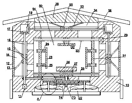
[0014] Combine below Figure 1-3 The present invention is described in detail, and for convenience of description, the orientations mentioned below are now stipulated as follows: figure 1 The up, down, left, right, front and back directions of the projection relationship itself are the same.
[0015] refer to Figure 1-3 According to an embodiment of the present invention, an automatic heat dissipation and moisture-proof power distribution cabinet installation box includes a main box body 10, and an installation cavity 50 is opened in the main box body 10, and two slidingly arranged in the installation cavity 50 A set of left and right symmetrical slide plates 51, two groups of slide plates 51 are provided with splints 23 for sliding on the sides close to each other, and the splints 23 are used to clamp the power distribution cabinet. Fixed block 27, a row of rollers 26 are rotated on the top surface of said fixed block 27, side cavities 14 are provided on the left and right sides of said main box body 10, and first The sealing plate 12, the side chamber 14 communicates with the installation chamber 50, the side chamber 14 can seal the side chamber 14, the top surface of the main box body 10 is provided with a top chamber 34, the top The cavity 34 communicates with the installation cavity 50, and a second sealing plate 20 is slidably arranged in the top cavity 34, and the top of the top cavity 34 can be sealed by the second sealing plate 20, and the second sealing plate The top surface of 20 is fixed with rain shielding plate 56, and described rain shielding plate 56 is used for protecting the whole equipment and waterproof, and the bottom surface of described main box body 10 is provided with two groups of left and right symmetrical blowing cavities 22, and described blowing cavity A fan 41 is rotated in the cavity 22 , and the fan 41 can blow air into the installation cavity 50 .
[0016] Preferably or exemplarily, two groups of first threaded blocks 15 symmetrical up and down are slidingly provided in the two groups of side cavities 14, and the first threaded blocks 15 and the first sealing plate 12 are connected by a second A connecting rod 13 is hinged together, and a sealed motor 11 is fixedly embedded in the bottom wall of the side chamber 14 on the left side, and a vertical screw 16 extending up and down is arranged in the side chamber 14, and the vertical screw rod 16 is located in the vertical screw rod 16 is threadedly connected with the first threaded block 15, and the vertical screw 16 on the left side is connected with the power of the sealing motor 11, and the first sealing plate 12 can be slid through the operation of the sealing motor 11 , so that the side cavity 14 is not blocked and sealed by the first sealing plate 12 .
[0017] Beneficially or exemplarily, two sets of left-right symmetrical second threaded blocks 55 are slidably arranged on the bottom wall of the top chamber 34, and a horizontal screw 54 is rotated inside the top chamber 34, and the horizontal screw 54 is connected with the The second threaded block 55 is threadedly connected, and a second connecting rod 53 is hinged between the second threaded block 55 and the bottom surface of the second sealing plate 20, and the top ends of the two sets of vertical screws 16 are fixed. There is a power bevel gear 17, and the left and right ends of the horizontal screw 54 are fixed with a driven bevel gear 19, the driven bevel gear 19 meshes with the power bevel gear 17, and through the rotation of the horizontal screw 54, The second sealing plate 20 can move up and down, so that the top chamber 34 will not be sealed.
[0018] Beneficially or exemplarily, an air inlet 42 is communicated between the blowing chamber 22 and the installation chamber 50, and a fixed disk 37 is fixed inside the air inlet 42, and a fixed disk 37 is set on the fixed disk 37. There is a first port 38, and the bottom wall of the installation cavity 50 is provided with a turntable 36, and the turntable 36 is provided with a second port 35, and the second port 35 can be connected with the first port. 38 overlap, the top of the turntable 36 and the vertical screw 16 on the left side are connected by the power of the first belt 71, and the bottom surfaces of the two sets of fixed disks 37 are equipped with fan shafts 39, and the fans 41 Fixed on the outer circumference of the fan shaft 39, a blower motor 73 is fixedly embedded in the main box 10, the top of the blower motor 73 is connected with a power pulley 74, and the power pulley 74 is connected to the The fan shafts 39 are connected by the second belt 40, through the work of the sealing motor 11, the second port 35 is overlapped with the first port 38, and the blower motor 73 is controlled to work, so that the Fan 41 rotates and blows air.
[0019] Beneficially or exemplarily, the fixed block 27 is fixed with a guide shaft 28 extending left and right, the guide shaft 28 runs through the slide plate 51 and is slidably fitted with the slide plate 51, two sets of the slide plates 51 A sliding post 25 is provided for sliding inside, and the sliding post 25 is fixed to one side of the clamping plate 23. The outer circumference of the sliding post 25 is provided with a spring 24, and one end of the spring 24 is fixed to the clamping plate 23. One end is fixed to the slide plate 51, a clamping motor 29 is fixedly embedded in the right wall of the installation cavity 50, and a power screw shaft 33 extending to the left is dynamically connected to the left end of the fan shaft 39, and the power screw shaft The shaft 33 runs through the two sets of slide plates 51 and is threadedly connected with them. The top wall of the installation cavity 50 is fixed with a power connection plate 32 for connecting wires and power connectors.
[0020] When in use, first put the power distribution cabinet into the installation cavity 50, and then control the clamping motor 29 to work, so that the two sets of slide plates 51 are close to each other, so that the splint 23 clamps the power distribution cabinet, and the rollers 26 play a convenient role. The function of pushing into the power distribution cabinet, when heat dissipation and ventilation are required, the sealing motor 11 is controlled to rotate, so that the vertical screw 16 rotates, and then the two groups of first threaded blocks 15 are close to each other, so that the first sealing plate 12 is opened, so that The outside world communicates with the installation cavity 50 through the side cavity 14, and at the same time, the driven bevel gear 17 drives the driven bevel gear 19 to rotate, and then the horizontal screw 54 rotates, so that the two sets of second threaded blocks 55 are close to each other, and the second sealing plate 20 is moved upward. , so that the top chamber 34 communicates with the outside world, and the vertical screw 16 drives the turntable 36 to rotate, so that the second port 35 overlaps with the first port 38, so that the blowing chamber 22 communicates with the installation chamber 50, and simultaneously controls the work of the blowing motor 73, so that The power pulley 74 rotates, and then the fan 41 rotates to blow air and dissipate heat. When it is raining or the weather is relatively humid, the second sealing plate 20 and the first sealing plate 12 are all in a closed state to prevent moisture in the installation cavity 50 .
[0021] The beneficial effects of the present invention are: the present invention can operate the sealing motor when the weather is relatively humid or rainy, so that the first sealing plate and the second sealing plate move simultaneously, and the side chamber and the top chamber are sealed, so that the humid air cannot enter the installation In the cavity, the power distribution cabinet is prevented from getting damp. At the same time, the rollers can facilitate the insertion and removal of the power distribution cabinet for maintenance. The electric board is connected, and the present invention has simple structure, stable transmission, convenient operation and easy popularization.
[0022]It will be clear to those skilled in the art that various modifications to the above embodiments can be made without departing from the general spirit and concept of the present invention. They all fall within the protection scope of the present invention. The protection scheme of the present invention shall be based on the appended claims of the present invention.

PUM

no PUM

Description & Claims & Application Information

We can also present the details of the Description, Claims and Application information to help users get a comprehensive understanding of the technical details of the patent, such as background art, summary of invention, brief description of drawings, description of embodiments, and other original content. On the other hand, users can also determine the specific scope of protection of the technology through the list of claims; as well as understand the changes in the life cycle of the technology with the presentation of the patent timeline. Login to view more.

Similar technology patents

Classification and recommendation of technical efficacy words

  • Simple structure
  • Prevent moisture

Microlithographic projection exposure apparatus

InactiveUS20050068499A1Simple structureReliable and low-maintenance operationProjectorsPhotomechanical exposure apparatusCamera lensPhysics
Owner:CARL ZEISS SMT GMBH

Electronic paper apparatus

InactiveUS20080062506A1Prevent moistureEnhanced moisture resistanceNon-linear opticsOptical elementsClosed spaceElectronic paper
Owner:GIGNO TECH CO LTD

Continuous, quantitative and rotary feeder

InactiveCN106629126APrevent moisture from entering the material binPrevent moistureLoading/unloadingEngineeringMoisture
Owner:吴云萍
Why Eureka
Try Eureka