
Moisture-proof and shock-absorbing communication equipment

A technology of communication equipment and shock-absorbing springs, which is applied in the construction parts of electrical equipment, cooling/ventilation/heating transformation, electrical components, etc., and can solve the problems of poor shock-absorbing effect of communication equipment, single upper and lower shock-absorbing structures, and affecting work, etc. , to achieve the effect of avoiding normal work, preventing damage and preventing bumps

Inactive Publication Date: 2020-02-28
江苏中高俊聪通信科技有限公司
View PDF5 Cites 1 Cited by
  • Summary
  • Abstract
  • Description
  • Claims
  • Application Information

AI Technical Summary

Problems solved by technology

[0006] The purpose of the present invention is to provide a moisture-proof and shock-absorbing communication device to solve the problem that the traditional vehicle-mounted communication device is not directly installed on the top of the accompanying vehicle, and it often encounters rainy and snowy weather, which easily causes the interior of the wireless communication device to be damp. In turn, it affects its normal work. At the same time, if it encounters a bumpy road section during the driving of the accompanying vehicle, the shock absorption effect of the communication equipment is relatively poor. Often there is only a single up and down shock absorbing structure, and there is no adjustment for the left and right shaking and bumps. Effective shock-absorbing treatment, which causes the internal structure of communication equipment to be easily damaged, which in turn greatly reduces the service life of communication equipment

Method used


Image

  • Moisture-proof and shock-absorbing communication equipment
  • Moisture-proof and shock-absorbing communication equipment
  • Moisture-proof and shock-absorbing communication equipment

Examples


Embodiment Construction

[0021] The following will clearly and completely describe the technical solutions in the embodiments of the present invention with reference to the drawings in the embodiments of the present invention.

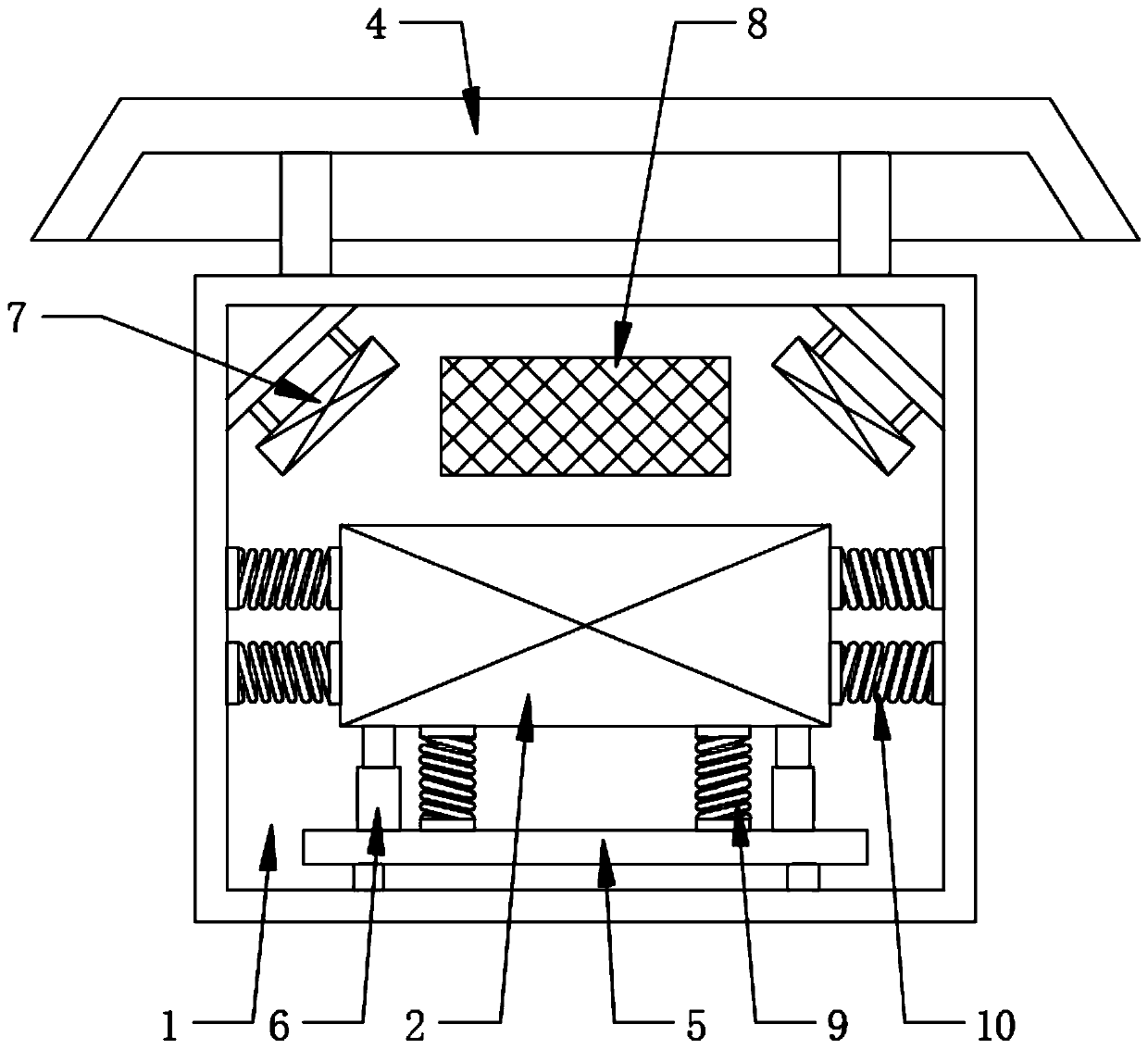
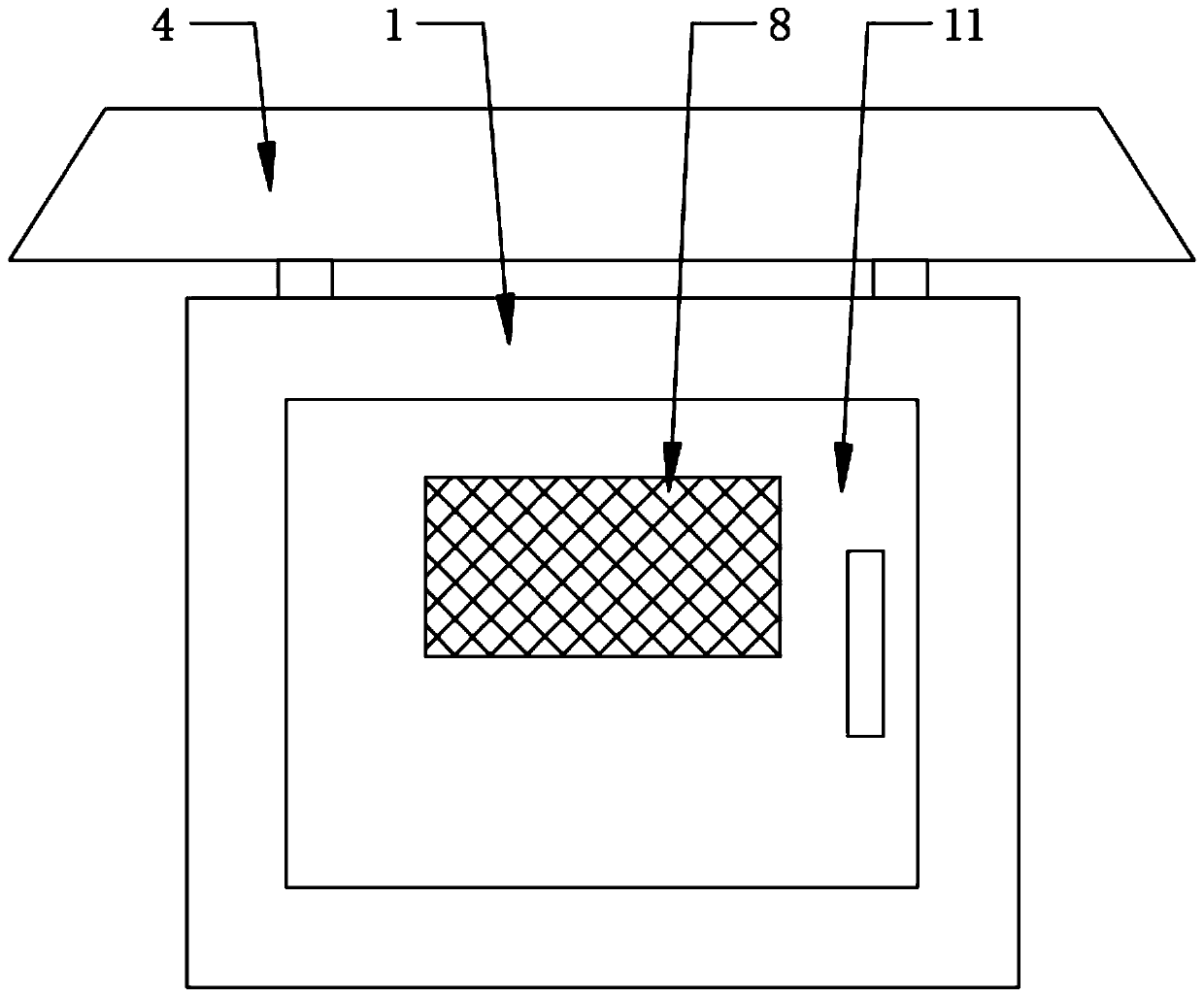
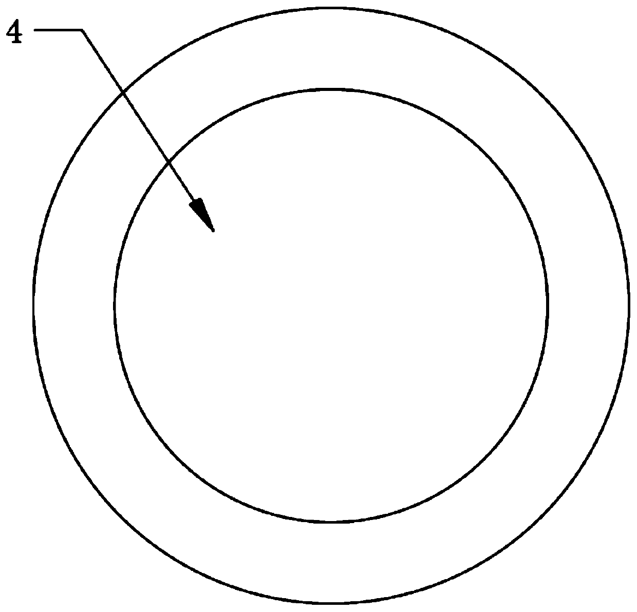
[0022] Such as Figure 1-4 As shown, a moisture-proof and shock-absorbing communication device includes a box body 1, a main body 2, a ventilation structure, a first shock-absorbing structure, and a second shock-absorbing structure. The inside of the box body 1 is provided with an installation cavity, and the box body 1 The inner bottom of the body 1 is horizontally provided with two chutes 3, and the top of the box body 1 is equipped with a rainproof cover 4 through the supporting legs, the rainproof cover 4 is circular, and the rainproof cover 4 The surrounding sides are set at an oblique angle toward the outside, the main body 2 is installed inside the box body 1 through the flexible connection between the installation structure and the two chute 3, the ventilation structur...


PUM


Abstract

The invention discloses moisture-proof and shock-absorbing communication equipment. The equipment comprises a box body, a main body, a ventilation structure, a first damping structure and a second damping structure, wherein a mounting cavity is formed in the box body, two sliding grooves are transversely formed at a bottom end of the interior of the box body, a rainproof cover is mounted at the top of the box body through supporting legs, the rainproof cover is circular, peripheral side surfaces of the rain-proof cover are arranged in a manner of inclining towards an outer part of the rain-proof cover, the main body is installed in the box body through movable connection of an installation structure and the two sliding grooves, the ventilation structures are fixedly installed on two sidesin the box body, the ventilation structures are located at the included angles between the top and the two sides of the box body, and the first damping structures are installed between the main body and the installation structure. The equipment is advantaged in that the protection effect on the communication equipment is good, the communication equipment is prevented from being affected by moisture, moreover, the communication equipment is prevented from being damaged due to jolt, and thereby the service life of the communication equipment is prolonged.

Description

technical field [0001] The invention relates to the field of communication equipment, in particular to a moisture-proof and shock-absorbing communication equipment. Background technique [0002] Communication equipment is wired communication equipment and wireless communication equipment used in industrial control environments. It is roughly divided into wired communication and wireless communication equipment. In some industries, it is necessary to often go to relatively remote places for operations. At this time, the accompanying vehicles Wireless communication equipment is generally installed on the top to enhance the signal strength in remote locations and facilitate better information exchange and communication with the outside world. [0003] However, the existing vehicular communication equipment has the following disadvantages: [0004] 1. Since the wireless communication device is directly installed on the top of the accompanying vehicle, it often encounters rain a...

Claims


Application Information

Patent Timeline
Patent Type & Authority Applications(China)
IPC IPC(8): H05K5/02H05K7/20B60R11/02
CPCB60R11/02B60R2011/004B60R2011/008H05K5/02H05K7/20H05K7/20136
Inventor 王斗
Owner 江苏中高俊聪通信科技有限公司
Learn More