

Self-cleaning stirring device
A stirring device, self-cleaning technology, used in mixers with rotary stirring devices, mixer accessories, transportation and packaging, etc.
- Summary
- Abstract
- Description
- Claims
- Application Information
AI Technical Summary
Problems solved by technology
Method used
Image

Examples
Embodiment 1
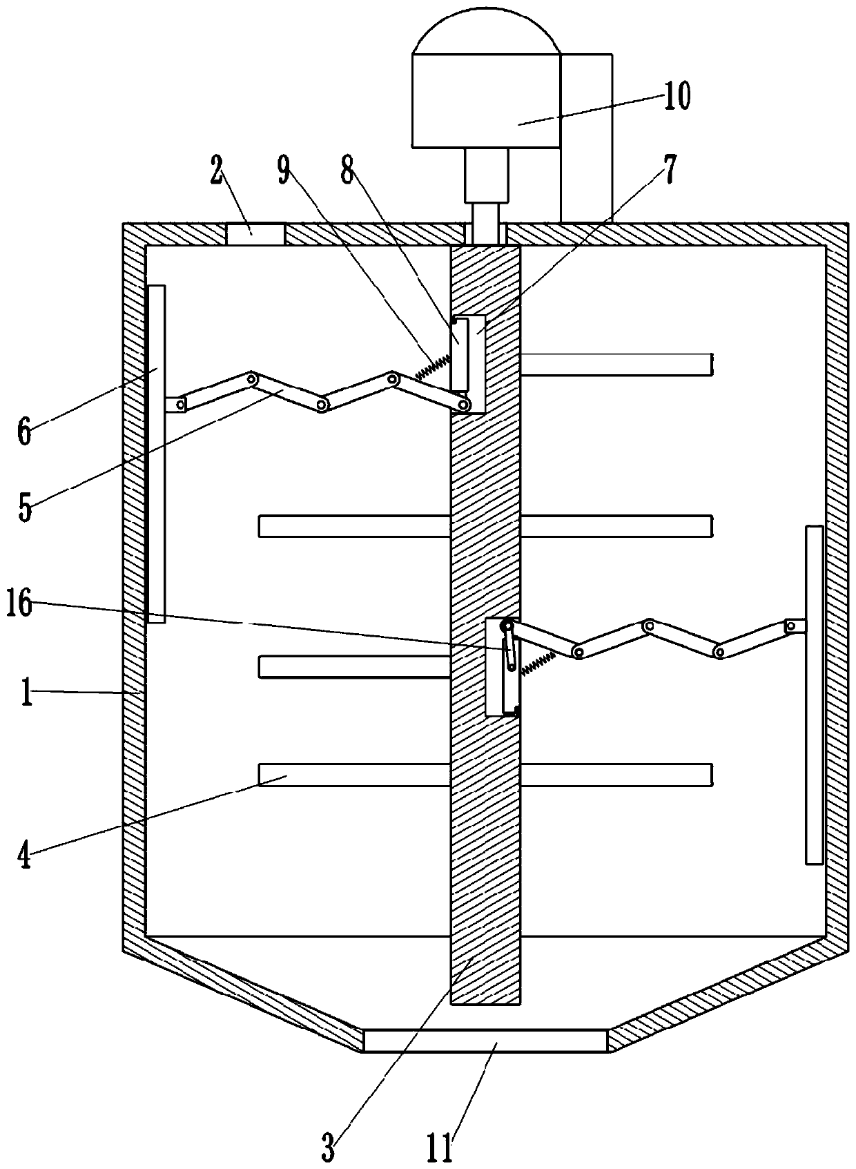
[0030] as attached figure 1 Shown: a self-cleaning stirring device, including a storage tank 1, the top of the storage tank 1 is provided with a feed inlet 2 for feeding, and the bottom of the storage tank 1 is provided with a frustum-shaped transition section, the transition section The bottom of the bottom is provided with the discharge port 11 that is used for unloading, and the valve plate (not shown) is connected with horizontal sliding in the discharge port 11. Stirring shaft 3 is connected to storage cylinder 1 through bearing rotation, and motor 10 is fixedly connected to storage cylinder 1 through bolts, and stepper motor 10 is selected here, and the output shaft of motor 10 is clamped and fixed with the upper end of stirring shaft 3, and the stirring A stirring rod 4 is fixedly clamped on the peripheral wall of the shaft 3 .
[0031] The peripheral surface of the stirring shaft 3 is also fixedly provided with a telescopic mechanism, and the free end of the telescopi...
Embodiment 2
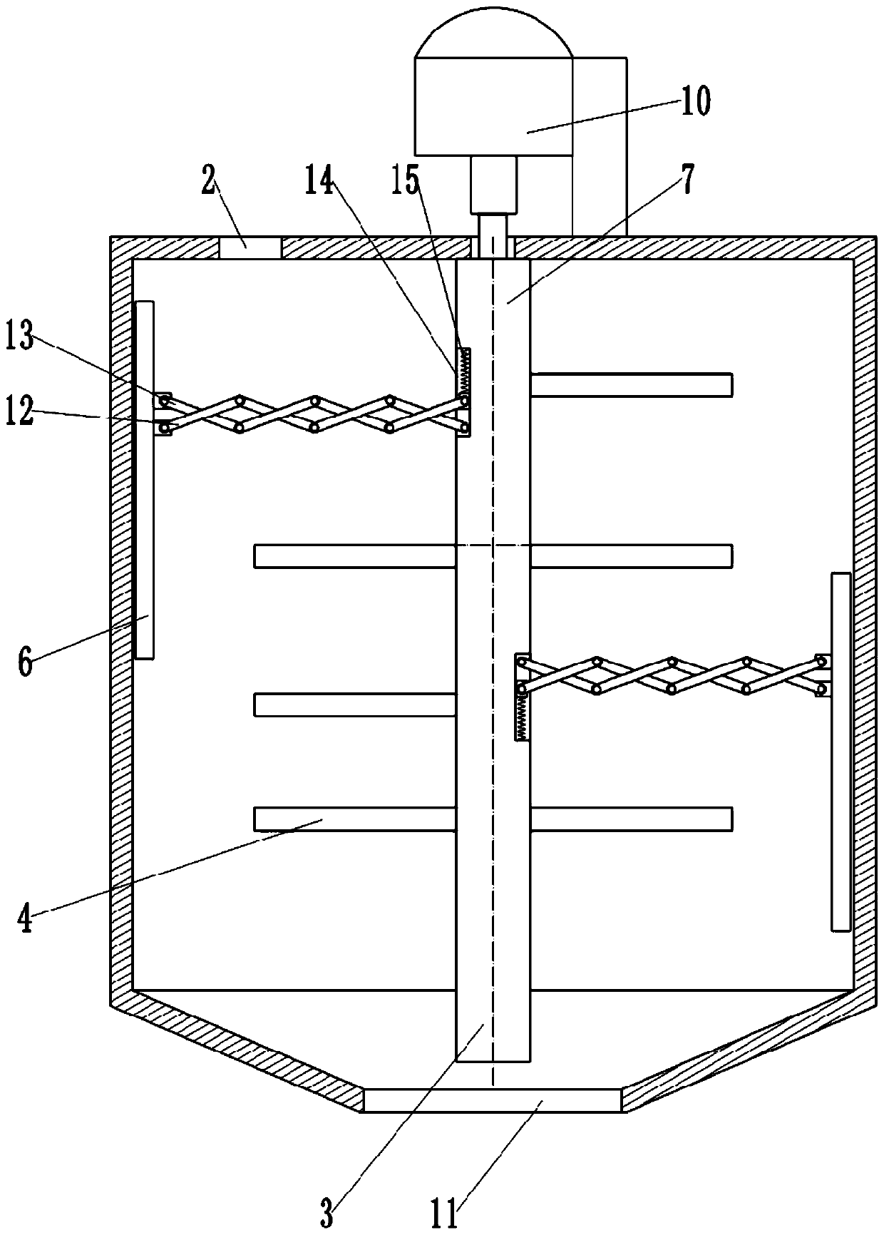
[0038] Such as figure 2 As shown, the difference between this embodiment and Embodiment 1 is that the telescopic mechanism includes a first hinged rod group 12 and a second hinged rod group 13 that are hinged to each other, and the first hinged rod group 12 and the second hinged rod group 13 have the same structure. Each includes several end-to-end hinged connecting rods, and four end-to-end hinged connecting rods are shown in the figure as an example. Take the telescopic mechanism on the left as an example below to illustrate the specific structure of the telescopic mechanism. A chute 14 is arranged on the peripheral wall of the stirring shaft 3 in the axial direction, and the left end of the first hinged rod group 12 is hinged to the scraper 6 through a pivot pin. , the right end of the first hinged rod group 12 is hinged to the inside of the chute 14 through the pivot pin; Straight sliding connection, the right end of the second hinged rod group 13 is hinged with a second...
Embodiment 3
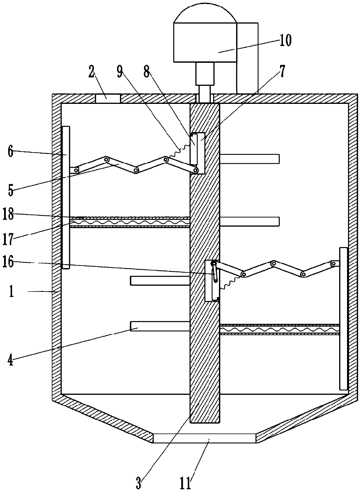
[0041] Such as image 3 As shown, the difference between this embodiment and Embodiment 1 is that a second elastic reset member 17 is provided between the scraper 6 and the stirring shaft 3, and the second elastic reset member 17 is a tension spring, which is named as the third for ease of distinction here. Extension spring, the outer periphery of the second elastic reset member 17 is provided with a protective sleeve 18, and the protective sleeve 18 is made of elastic rubber material with smooth appearance. The second elastic reset member 17 of this solution can provide support for the scraper 6, so that the rotation of the scraper 6 is more stable, and can also provide power for the scraper 6 to draw in the stirring shaft 3, so that the distance between the scraper 6 and the stirring shaft 3 The telescopic mechanism between them can be folded more thoroughly; at the same time, the second elastic reset member 17 of this solution rotates around the stirring shaft 3, and can al...
PUM
 Abstract
Description
Claims
Application Information