Automotive full-automatic protection cover

A fully automatic, protective cover technology, applied in the direction of movable outer sheath, vehicle parts, transportation and packaging, etc., can solve the problems of high labor intensity, complicated operation, complex and bulky structure, etc., to reduce failures and ensure stability. , the effect of improving efficiency

Pending Publication Date: 2020-03-06
王光军
View PDF0 Cites 0 Cited by
  • Summary
  • Abstract
  • Description
  • Claims
  • Application Information

AI Technical Summary

Problems solved by technology

Due to various restrictions such as insufficient garages and travel needs, a large number of cars often need to be parked in the open air. As the seasons change, the cars are affected by the sun, rain, frost, snow, fog, etc., which will speed up the damage of the car body. Aging of paint and interior decoration
However, the structure of the current car cover is complex and heavy, and it is inconvenient to open the car cover to cover the car body and store the car cover. When one person covers the car cover, the operation is complicated and labor-intensive; Folding the car cover makes folding and storing complicated

Method used


Image

  • Automotive full-automatic protection cover
  • Automotive full-automatic protection cover
  • Automotive full-automatic protection cover

Examples


Embodiment 1

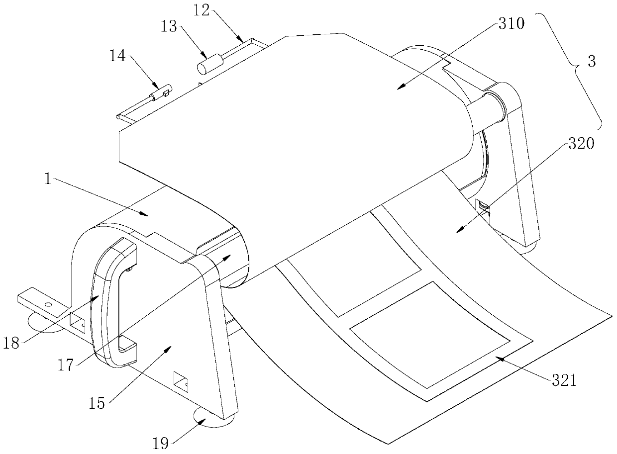
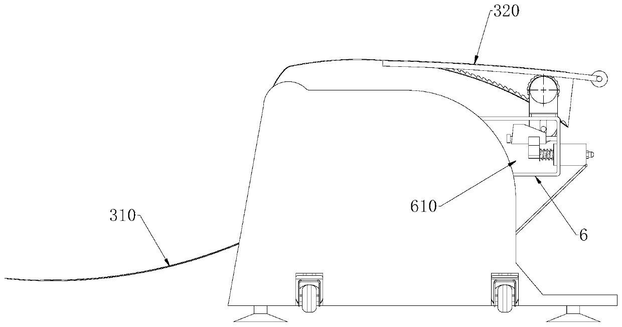
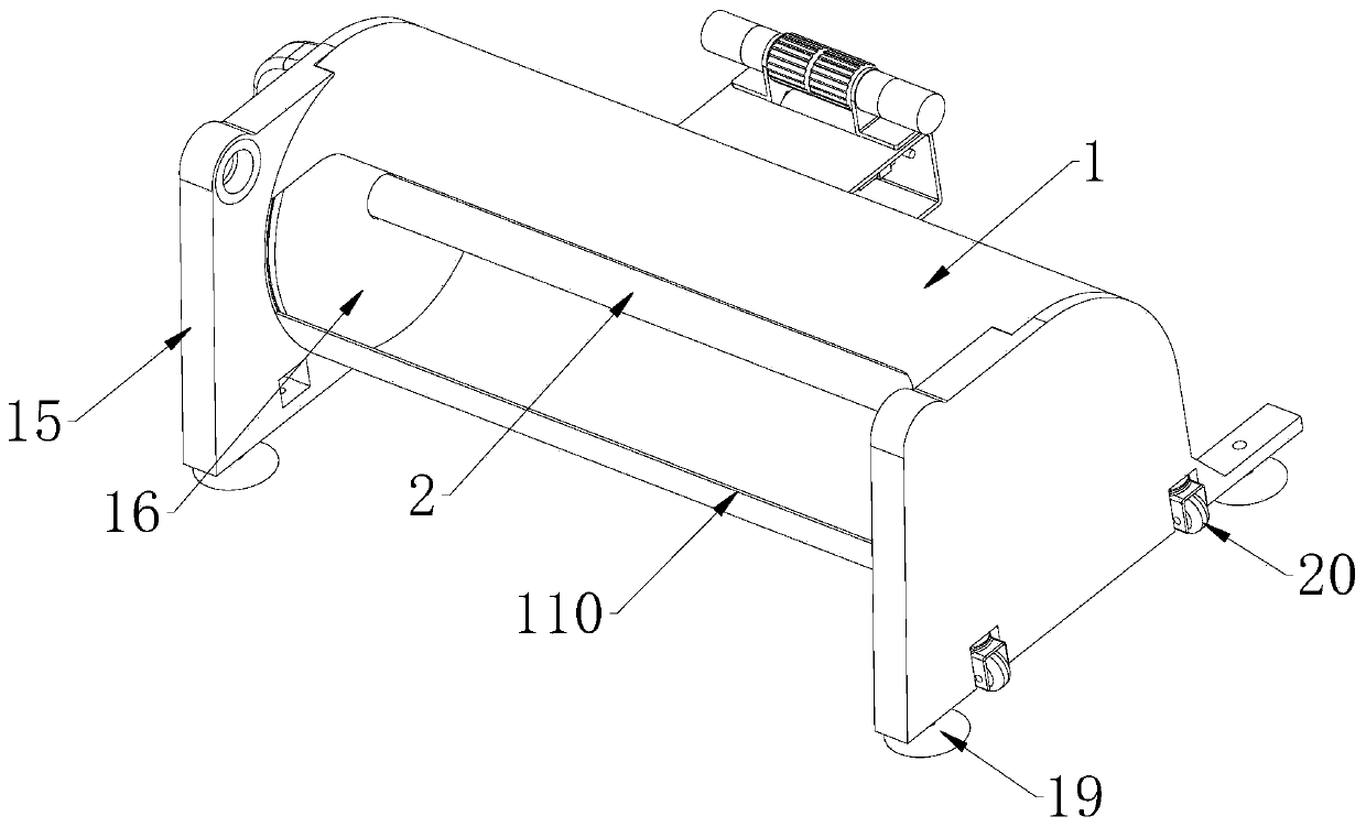
[0041] The fully automatic protective cover for vehicles of the present invention comprises a collection tube 1 located at the upper end of the vehicle body, a central shaft 2 is arranged to rotate inside the collection tube 1, a car body 3 is connected to the central shaft 2, and an opening is provided on the side wall of the collection tube 1 110; the cover body 3 is folded and wound on the central axis 2, the cover body 3 protrudes from the opening 110 to form the first cover 310 and the second cover 320 facing away from the back, and the first cover 310 is provided with The toothed belt 4 is provided with a gap between the toothed belt 4 and the first car cover 310, and the lower end of the first car cover 310 is connected with a connecting cloth 5, and the toothed belt 4 and the first car cover 310 are connected to each other by the connecting cloth 5, and the collected The outer wall of the barrel 1 is provided with a fixed frame 6, and the fixed frame 6 is provided with ...

Embodiment 2

[0044] This embodiment is further optimized on the basis of Embodiment 1 as follows: the profile of the connecting cloth 5 is T-shaped, the upper end of the connecting cloth 5 is connected to the first car cover 310, and the lower end of the connecting cloth 5 is connected to the first car cover. 310 are parallel to each other, two toothed belts 4 are arranged side by side, and the two toothed belts 4 are respectively located on the left and right sides of the connecting cloth 5; the left and right sides of the connecting cloth 5 are symmetrically provided with a driving unit 7, and the driving unit 7 includes a reduction motor 730, The motor bracket 720 and the gear 710, the reduction motor 730 and the fixed frame 6 are connected to each other through the motor bracket 720, the gear 710 is sleeved on the drive shaft of the reduction motor 730, the gear 710 is located in the gap, and the gear 710 and the toothed belt 4 mesh with each other .

[0045] After adopting the above t...

Embodiment 3

[0047] This embodiment is further optimized on the basis of Embodiment 1 as follows: a placement groove is formed between the fixed frame 6 and the outer wall of the collection tube 1, the toothed belt 4 is located above the placement groove, and the fixed frame 6 is provided with a groove for easy compression. The through hole for the lifting and moving of the wheel 8. The lower ends of the two motor brackets 720 extend into the placement groove after penetrating the fixed frame 6. The motor brackets 720 are provided with chute 721 along the vertical direction, and the two chute 721 are provided with There is a pressing wheel shaft 810, and the pressing wheel 8 is rotatably sleeved on the outside of the pressing wheel shaft 810, and the outer sides of the two chutes 721 are respectively provided with jacking units 9.

[0048] After adopting the above technical solution: the fixed frame 6 is formed by bending the upper and lower ends of a plate towards the direction close to th...


PUM


Abstract

The invention discloses an automotive full-automatic protection cover, and relates to the technical field of automotive protection covers. The automation degree that automobile bodies are covered withautomobile covers is increased, and labor burdens of users are relieved. The automotive full-automatic protection cover comprises a collection barrel located at the upper end of an automobile body, acenter shaft is rotationally arranged in the collection barrel, an automobile cover body is connected to the center shaft, and an opening is formed in the side wall of the collection barrel. The automobile cover body is folded and wound on the center shaft, the automobile cover body stretches out from the opening to from a first automobile cover and a second automobile body which back on to eachother. A toothed belt is arranged below the first automobile cover. A gap is arranged between the toothed belt and the first automobile cover. The lower end of the first automobile cover is connectedwith connecting cloth. The toothed belt and the first automobile cover are connected through the connecting cloth. A fixed frame is arranged on the outer wall of the collection barrel, a drive unit cooperating with the toothed belt is arranged on the fixed frame, and a pressing wheel capable of achieving lifting motion is arranged at the lower end of the toothed belt.

Description

technical field [0001] The invention relates to the technical field of automobile protective cover devices, in particular to a fully automatic protective cover for vehicles. Background technique [0002] With the improvement of people's living standards, automobiles have become a means of transportation for human beings. Due to various restrictions such as insufficient garages and travel needs, a large number of cars often need to be parked in the open air. As the seasons change, the cars are affected by the sun, rain, frost, snow, fog, etc., which will speed up the damage of the car body. Aging of paint and interior decorations. However, the structure of the current car cover is complex and heavy, and it is inconvenient to open the car cover to cover the car body and store the car cover. When one person covers the car cover, the operation is complicated and labor-intensive; Folding the car cover makes folding and storing complicated. [0003] For this reason, there is an...

Claims


Application Information

Patent Timeline
Patent Type & Authority Applications(China)
IPC IPC(8): B60J11/02
CPCB60J11/02
Inventor 王光军
Owner 王光军
Why Eureka
Try Eureka