Hydraulic shaping device and shaping method

A shaping device and hydraulic technology, used in earth-moving drilling, wellbore/well components, etc., can solve the problems of insufficient shaping force and small shaping area, and achieve the effects of low cost of use, large shaping area, and safe and reliable tools

Pending Publication Date: 2020-03-06
GUIZHOU GAOFENG GASOLINEEUM MACHINERY
View PDF0 Cites 0 Cited by
  • Summary
  • Abstract
  • Description
  • Claims
  • Application Information

AI Technical Summary

Problems solved by technology

[0004] The purpose of the present invention is to provide a hydraulic shaping device and shaping method to solve the problems

Method used


Image

  • Hydraulic shaping device and shaping method

Examples


Embodiment Construction

[0013] The present invention will be further described in detail below with reference to the drawings and embodiments.

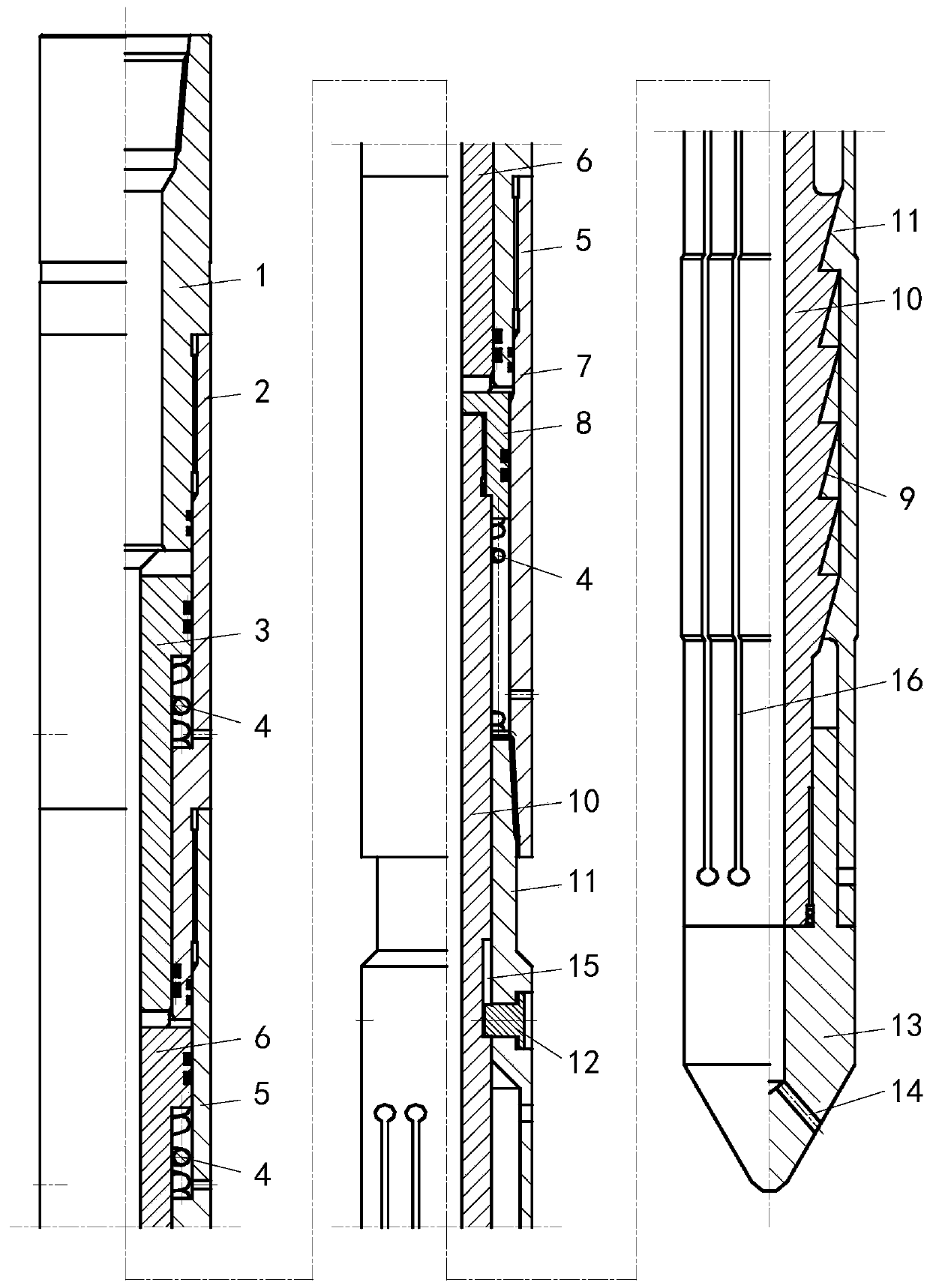
[0014] A hydraulic shaping device of the present invention, such as figure 1 As shown, the device includes two parts: an outer tube and a core tube located in the outer tube; an upper joint 1, an upper piston cylinder 2, a lower piston cylinder 5, an outer sleeve 7 and a shaping jacket 11 which are threadedly connected from top to bottom in the outer tube The core tube includes an upper piston rod 3, a lower piston rod 6, a connecting sleeve 8 and a shaping mandrel 10 from top to bottom; the bottom end of the shaping mandrel 10 is connected with the lead cone 13; the lead cone 13 is provided with lateral water Eye 14; between the outer boss of the upper piston rod 3 and the inner boss of the upper piston cylinder 2, the outer boss of the lower piston rod 6 and the inner boss of the lower piston cylinder 5, and the bottom end of the connecting sleeve 8 and shapi...


PUM


Abstract

The invention discloses a hydraulic shaping device and a shaping method. The hydraulic shaping device comprises an outer pipe and a core pipe positioned in the outer pipe, wherein the outer pipe is composed of an upper connector (1), an upper piston cylinder (2), a lower piston cylinder (5), an outer sleeve (7) and a shaping outer sleeve (11) which are sequentially in threaded connection from topto bottom; the core pipe comprises an upper piston rod (3), a lower piston rod (6), a connecting sleeve (8) and a shaping mandrel (10) which are arranged from top to bottom; the bottom end of the shaping mandrel is connected with a guide cone (13); a lateral water hole (14) is formed in the guide cone; springs (4) are arranged between an outer boss of the upper piston rod and an inner boss of theupper piston cylinder, between an outer boss of the lower piston rod and an inner boss of the lower piston cylinder and between the bottom end of the connecting sleeve and the top end of the shaping outer sleeve; and the shaping outer sleeve and the shaping mandrel are connected through a sawtooth-shaped large screw (9). The hydraulic shaping device has the beneficial effects of being simple in structure, convenient to use, low in cost and convenient to maintain. The operation process is safe and reliable.

Description

Technical field [0001] The invention relates to a hydraulic shaping device and a shaping method, and belongs to the technical field of drilling equipment. Background technique [0002] In oil well operations, the casing and tubing will always be deformed in a certain section after being used for a period of time. The deformed casing or tubing will affect the operation of the oil well. So it needs to be repaired. The traditional repair method is to mill out the deformed casing or tubing section with a tool, and then patch a new casing or tubing. The traditional repair method is expensive and consumes a lot of manpower and material resources. [0003] In order to reduce repair costs, a shaping device for repairing deformed casing or tubing appears. Existing shaping devices are mainly mechanical and hydraulic, but the existing shaping devices generally have the disadvantages of insufficient shaping force or too small shaping area, and often fail to meet the requirements of shaping o...

Claims


Application Information

Patent Timeline
IPC IPC(8): E21B29/10
CPCE21B29/10
Inventor 张腾飞黄保黔郑波强王文郑廷碧
Owner GUIZHOU GAOFENG GASOLINEEUM MACHINERY
Why Eureka
Try Eureka