Anti-collision power distribution cabinet convenient to move

A power distribution cabinet and anti-collision technology, which is applied in the substation/power distribution device shell, electrical components, animal repellent, etc., can solve the problem that the distance between the installation boards of the power distribution cabinet cannot be adjusted, and the cabinet body is easily polluted by bird droppings, etc. problem, to achieve the effect of solving the non-adjustable spacing and avoiding bird droppings pollution

Inactive Publication Date: 2020-03-06
NANYANG POWER SUPPLY COMPANY OF STATE GRID HENAN ELECTRIC POWER
View PDF7 Cites 5 Cited by
  • Summary
  • Abstract
  • Description
  • Claims
  • Application Information

AI Technical Summary

Benefits of technology

The present invent describes an improved design for electrical equipment cabinets used at different locations within buildings or facilities where they are installed. This helps reduce collisions caused during construction without causing harm to other parts inside it. It also prevents insects getting into the machine while still working properly. Additionally, this technology allows for easy movement around when installing new components due to its ability to allow for easier accessibility through rolling mechanisms. Overall, these improvements improve safety measures and make maintenance more efficient over time.

Problems solved by technology

Power Distribution cabinets have been developed over time with different technical features that aim at protecting loads from damage caused by birds or other factors such as rainwater falling on them during construction work hours. However, these cabinets can only allow limited movement within their range due to its design without allowing any changes if needed.

Method used


Image

  • Anti-collision power distribution cabinet convenient to move
  • Anti-collision power distribution cabinet convenient to move
  • Anti-collision power distribution cabinet convenient to move

Examples


Embodiment 1

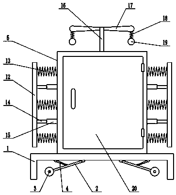
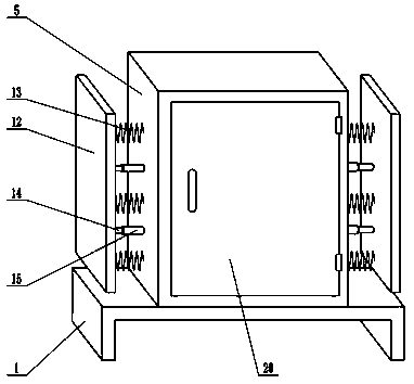
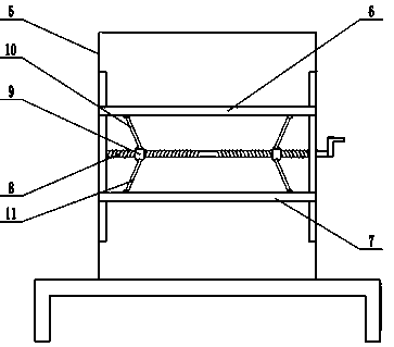
[0020] see Figure 1-3 , in the embodiment of the present invention, an anti-collision power distribution cabinet that is easy to move includes a mounting frame 1, a cabinet body 5, an upper mounting plate 6, a lower mounting plate 7 and a cabinet door 20, and the upper surface of the mounting frame 1 is fixedly connected with The cabinet body 5 is equipped with an upper mounting plate 6 and a lower mounting plate 7 inside the cabinet body 5. The electronic components are installed on the upper mounting plate 6 and the lower mounting plate 7. The upper mounting plate 6 and the lower mounting plate 7 are installed horizontally. The ends of the plate 6 and the lower mounting plate 7 are slidingly connected with the inner wall of the cabinet body 5 respectively, the upper mounting plate 6 and the lower mounting plate 7 can slide up and down along the inner wall of the cabinet body 5, and the upper mounting plate 6 and the lower mounting plate 7 Two-way screw rod 8 is installed be...

Embodiment 2

[0022] On the basis of Embodiment 1, the lower surface of the mounting bracket 1 is hinged with a movable rod 2, and there are two movable rods 2, which are arranged symmetrically on the left and right. There are rollers, the lower surface of the mounting frame 1 is hinged with a telescopic mechanism 4, the telescopic mechanism 4 is an electro-hydraulic telescopic cylinder, the lower end of the telescopic mechanism 4 is hinged with the middle part of the movable rod 2, and the extension of the telescopic mechanism 4 is controlled to drive the movable rod 2 to rotate , thereby driving the roller 3 to move downward, so that the roller meets the ground, at this time, the device can be conveniently pushed to move the position.

Embodiment 1、 Embodiment 2

[0023] In combination with Embodiment 1 and Embodiment 2, the working principle of the present invention is: when it is necessary to install electronic components on the upper mounting plate 6 and the lower mounting plate 7, turn the handle to drive the two-way screw rod 8 to rotate, thereby driving the two sliders 9 Make opposite movement or backward movement, thereby driving the upper mounting plate 6 and the lower mounting plate 7 to move up and down, so as to adjust the distance between the upper mounting plate 6 and the lower mounting plate 7 according to the actual installation requirements, so as to facilitate the installation of electronic components. When the anti-collision plate 12 is impacted, the buffer spring 13 is compressed, which can absorb a part of the energy of the impact, and the buffer spring 13 can play the role of anti-collision, thereby protecting the cabinet body 5 from damage. When the wind blows, the fan blade 17 rotates , to drive the bell 19 to rota...


PUM


Abstract

The invention relates to the field of power equipment, and particularly relates to an anti-collision power distribution cabinet convenient to move. The anti-collision power distribution cabinet comprises a mounting frame, a cabinet body, an upper mounting plate, a lower mounting plate and a cabinet door. The upper surface of the mounting frame is fixedly connected with the cabinet body; the uppermounting plate and the lower mounting plate are mounted in the cabinet body; a bidirectional screw rod is mounted between the upper mounting plate and the lower mounting plate; the bidirectional screwrod is sleeved with a sliding block; an upper connecting rod is hinged to the upper surface of the sliding block; the upper end of the upper connecting rod is hinged to the lower surface of the uppermounting plate; a lower connecting rod is hinged to the lower end of the sliding block; the lower end of the lower connecting rod is hinged to the upper surface of the lower connecting rod; anti-collision plates are arranged at the left side and the right side of the cabinet body respectively; and the top portion of the cabinet body is provided with a bird repelling mechanism. According to the invention, the distance between the upper mounting plate and the lower mounting plate can be adjusted according to actual mounting requirements to facilitate installation of electronic components; the buffer springs can play an anti-collision role, so that the cabinet body is protected from being damaged; and birds are repelled by the bird repelling mechanism, and thus the device is prevented from being polluted by bird droppings.

Description


Claims


Application Information

Patent Timeline
Owner NANYANG POWER SUPPLY COMPANY OF STATE GRID HENAN ELECTRIC POWER
Why Eureka
Try Eureka