N-MOS and P-MOS permanent magnet synchronous motor driving circuit with hardware protection

A permanent magnet synchronous motor and drive circuit technology, applied in motor control, AC motor control, electrical components, etc., to achieve the effects of saving IO resources, improving reliability, and reducing operating pressure

Active Publication Date: 2020-03-06
BEIJING UNIV OF TECH
View PDF3 Cites 2 Cited by
  • Summary
  • Abstract
  • Description
  • Claims
  • Application Information

AI Technical Summary

Problems solved by technology

[0004] The purpose of the present invention is to solve the problems caused by using a power drive chip plus two power tubes in a traditional three-phase permanent magnet synchronous motor driver. This drive scheme requires the controller to output six complementary symmetrical PWM waves to control the power drive chip to drive up and down. The switching action of the bridge arm MOS tube

Method used


Image

  • N-MOS and P-MOS permanent magnet synchronous motor driving circuit with hardware protection
  • N-MOS and P-MOS permanent magnet synchronous motor driving circuit with hardware protection
  • N-MOS and P-MOS permanent magnet synchronous motor driving circuit with hardware protection

Examples


Embodiment Construction

[0035] The present invention will be further described below in conjunction with the drawings.

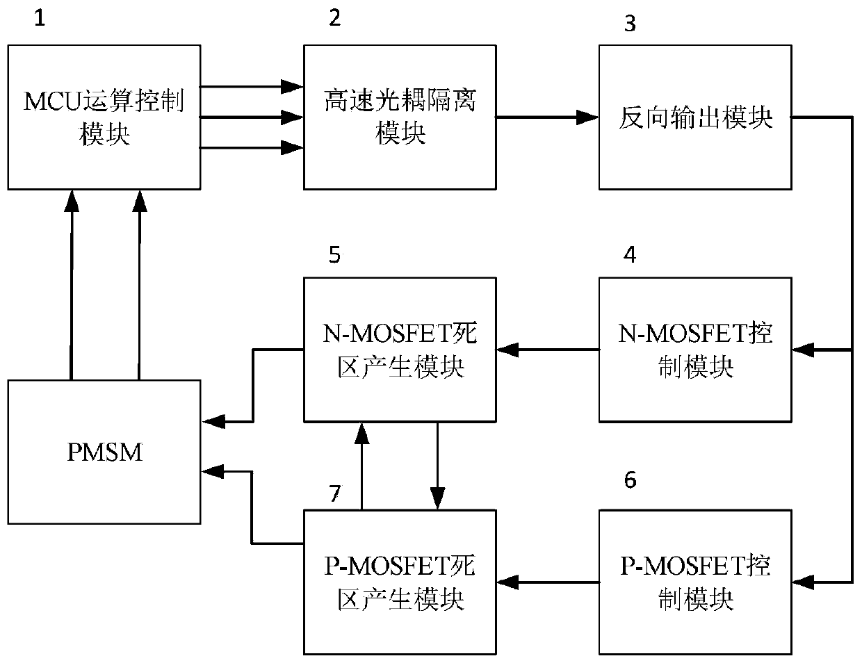
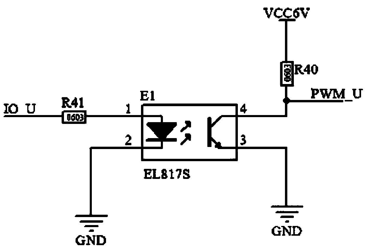
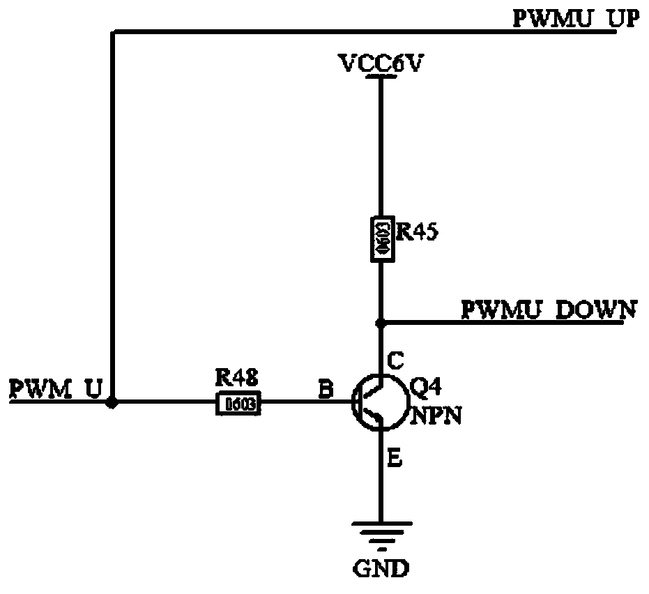
[0036] Such as figure 1 As shown, a permanent magnet synchronous motor drive circuit with hardware protection of N-NOSFET and P-MOSFET includes MCU operation control module (1), high-speed optocoupler isolation module (2), reverse output module (3), N-MOSFET control module (4), N-MOSFET dead zone generation module (5), P-MOSFET control module (6), P-MOSFET control module (7). The MCU operation control module outputs three-phase U, V, W three-way PWM waves into the high-speed optocoupler isolation module (2), taking the U phase as an example for explanation, the remaining two phases are the same as the U phase, and the optocoupler isolated PWM The signal enters the reverse output module (3), which reverses the output of the PWM signal to realize the output of two complementary and symmetrical PWM waves, one enters the lower bridge arm N-MOSFET control module (4), and the other enters t...


PUM


Abstract

The invention discloses a N-MOS and P-MOS permanent magnet synchronous motor driving circuit with hardware protection. According to the technical scheme, the novel permanent magnet synchronous motor driving circuit controls a three-phase permanent magnet synchronous motor to work and uses discrete components to drive an N-MOSFET and a P-MOSFET and comprises an MCU operation control module (1), a high-speed optical coupler isolation module (2), a reverse output module (3), an N-MOSFET control module (4), an N-MOSFET dead zone generation module (5), a P-MOSFET control module (6) and a P-MOSFET dead zone generation module (7). The middle-low grade MCU outputs a path of PWM wave, the PWM wave can be converted into two paths of complementary and symmetrical PWM waves with dead zones after passing through the driving circuit, and the power element is driven to control permanent magnet synchronous operation. According to the driving mode, the power driving chip is not used, the circuit cost is reduced, IO resources of the middle-low grade MCU are saved, the operation burden of the MCU is relieved and the generated dead zone time prevents upper and lower bridge arms from simultaneously conducting to cause circuit breakdown.

Description

Technical field [0001] The invention relates to a permanent magnet synchronous motor control circuit, in particular to drive control using N-channel MOS transistors and P-channel MOS transistors. The drive circuit has its own hardware protection function and can convert a channel of input PWM signal into Two complementary symmetrical PWM waves with dead zone, the dead zone time generated by the hardware circuit can effectively prevent the upper and lower bridge arm power tubes from being turned on at the same time. Background technique [0002] Permanent Magnet Synchronous Motor (PMSM) has the advantages of simple structure, small size, light weight, high power density and large output torque. It is widely used in robots, CNC machine tools, smart homes, new energy vehicles and other fields. With the continuous improvement and improvement of the performance of permanent magnet materials and power electronic components, the demand for various types of permanent magnet synchronous m...

Claims


Application Information

Patent Timeline
Patent Type & Authority Applications(China)
IPC IPC(8): H02M1/08H02M1/088H02M1/38H02M7/5387H02P25/022
CPCH02M1/08H02M1/088H02M1/38H02M7/53873H02P25/022H02P2207/05H02M1/0012
Inventor 石照耀张攀林家春于渤俞志勇
Owner BEIJING UNIV OF TECH
Why Eureka
Try Eureka