
Visual Drainage Tube Assembly

A drainage tube and component technology, applied in the field of visual drainage tube components, can solve the problems of blind penetration of drainage tube drainage, secondary damage, etc., and achieve the effect of avoiding secondary damage, avoiding blind penetration, and reducing dependence on experience

Active Publication Date: 2022-08-09
上海库欣医疗科技有限公司
View PDF7 Cites 0 Cited by
  • Summary
  • Abstract
  • Description
  • Claims
  • Application Information

AI Technical Summary

Problems solved by technology

[0009] The technical problem to be solved by the present invention is to provide a visible drainage tube assembly in order to overcome the defects of blind drainage tube drainage and easy secondary damage in the prior art

Method used


Image

  • Visual Drainage Tube Assembly
  • Visual Drainage Tube Assembly

Examples


Embodiment 1

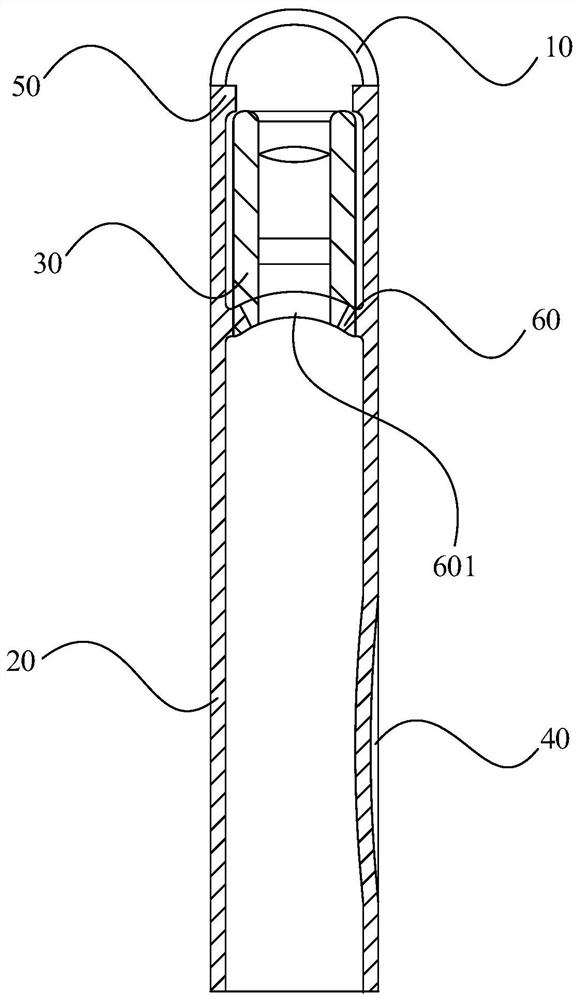
[0056] This embodiment provides a visual drainage tube assembly, which can be understood with reference to 1. The visual drainage tube assembly includes a visual tube head 10 , a tube body 20 and an endoscope 30 . The visual tube head 10 is made of a material with a light transmittance of not less than 80%. The tube body 20 has a head end and a tail end along the length direction, the head end of the tube body 20 is connected to the visual tube head 10, and the side wall of the tail end of the tube body 20 is provided with a drainage port 40 that communicates with the interior of the tube body 20. . The endoscope 30 is located inside the head end of the tubular body 20 .

[0057] In this embodiment, the tube body 20 does not hinder the imaging of the endoscope 30, and can protect the endoscope 30 to a certain extent, so that the process of puncturing the tube is as convenient and intuitive as the operation of the endoscope 30. It can avoid blind puncture in the process of ca...

Embodiment 2

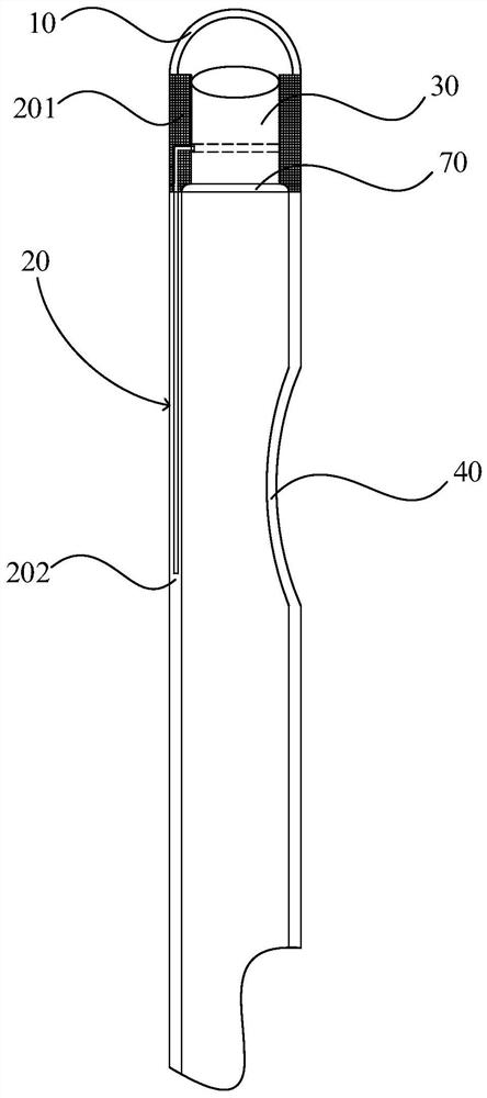
[0067] refer to figure 2 It should be understood that the structure of the visual drainage tube assembly in this embodiment is basically the same as the structure of the visual drainage tube assembly in Embodiment 1, and the difference lies in the positional relationship and connection relationship between the endoscope 30 and the tube body 20 .

[0068] Specifically, refer to figure 2 It should be understood that the tube body 20 includes a first part and a second part 202, the first part has a support 201 and an endoscope 30, the endoscope 30 is clamped and fixedly connected to the inside of the support 201, and the support 201 is connected to the Between the tube head 10 and the second part 202 , the drainage port 40 is provided in the second part 202 . In this embodiment, the endoscope 30 and the support member 201 are fixedly connected to form an integral structure, which is convenient to use.

[0069] Further, in this embodiment, the endoscope 30 is a CCD endoscope ...


PUM


Abstract

The invention discloses a visual drainage tube assembly. The visual drainage tube assembly includes a visual tube head, a tube body and an endoscope. The visual tube head is made of a material with a light transmittance of not less than 80%. The pipe body has a head end and a tail end along the length direction, the head end of the pipe body is connected to the visible pipe head, and the side wall of the tail end of the pipe body is provided with a drainage port which communicates with the interior of the pipe body. An endoscope is located inside the head end of the tubular body. The tube body does not hinder the imaging of the endoscope, and can protect the endoscope to a certain extent, making the process of puncturing the tube as convenient and intuitive as endoscopic surgery, avoiding blind penetration during the tube placement, reducing Relying on the experience of the clinician, it can reach the expected drainage position with minimal damage, and at the same time, it can avoid the unnecessary trouble of directly using the endoscope for re-insertion, which is conducive to avoiding secondary damage and is conducive to Improve tube placement efficiency.

Description

technical field [0001] The invention relates to medical instruments, in particular to a visual drainage tube assembly. Background technique [0002] There are many types of surgical drainage tubes in clinical practice, which are generally used in wounds, brain, neck, upper abdomen, lower abdomen, pelvis, lumbar cistern, gastrointestinal tract, biliary tract, etc. , appendicitis, colorectal cancer, cerebral hemorrhage, brain tumor, etc. The main purpose of drainage is to drain pus, blood, and body fluids accumulated between human tissues or body cavities to the outside of the body through the inner hole of the tube to prevent postoperative infection and a large amount of fluid accumulation in the body. Organization, etc. [0003] The main points of drainage tube placement include: (1) keep the drainage tube in the correct position; (2) keep the abdominal drainage tube unobstructed; (3) maintain the correct body position after surgery; (4) keep the dressing at the tube placem...

Claims


Application Information

Patent Timeline
Patent Type & Authority Patents(China)
IPC IPC(8): A61M25/00
CPCA61M25/0021A61M25/0043A61M25/0068A61M2025/0008
Inventor 孙树杰裴晓宏宋丽强张国峰
Owner 上海库欣医疗科技有限公司
Learn More