
Multi-machine parallel current sharing circuit and digital control switching power supply

A circuit and parallel technology, applied in emergency protection circuit devices, electrical components, conversion equipment without intermediate conversion to AC, etc., can solve the problems of low current sharing accuracy, high cost, difficult to discharge interference signals, etc., to achieve versatility Strong, low cost, high accuracy of current sharing

Pending Publication Date: 2020-03-13
深圳市英合科技有限公司
View PDF0 Cites 2 Cited by
  • Summary
  • Abstract
  • Description
  • Claims
  • Application Information

AI Technical Summary

Problems solved by technology

[0003] The inventor found in the process of studying this application that the switching power supply in the prior art either uses a dedicated current sharing chip for multi-machine parallel current sharing control, which has the disadvantages of poor versatility and high cost.
Either use the analog control mode, the accuracy of current sharing is not high, and it is not easy to discharge various interference signals

Method used


Image

  • Multi-machine parallel current sharing circuit and digital control switching power supply
  • Multi-machine parallel current sharing circuit and digital control switching power supply
  • Multi-machine parallel current sharing circuit and digital control switching power supply

Examples


Embodiment Construction

[0019] In order to facilitate the understanding of this application, the following will make a more comprehensive description of this application with reference to the relevant drawings. The preferred embodiments of the application are shown in the drawings. However, this application can be implemented in many different forms and is not limited to the embodiments described herein. On the contrary, the purpose of providing these embodiments is to make the understanding of the disclosure of this application more thorough and comprehensive.

[0020] Unless otherwise defined, all technical and scientific terms used herein have the same meaning as commonly understood by those skilled in the technical field of this application. The terminology used in the specification of the application herein is only for the purpose of describing specific embodiments, and is not intended to limit the application.

[0021] At present, in the need to use switching power supply and airport, the switchin...


PUM


Abstract

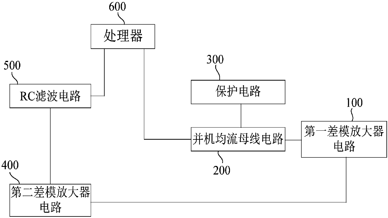
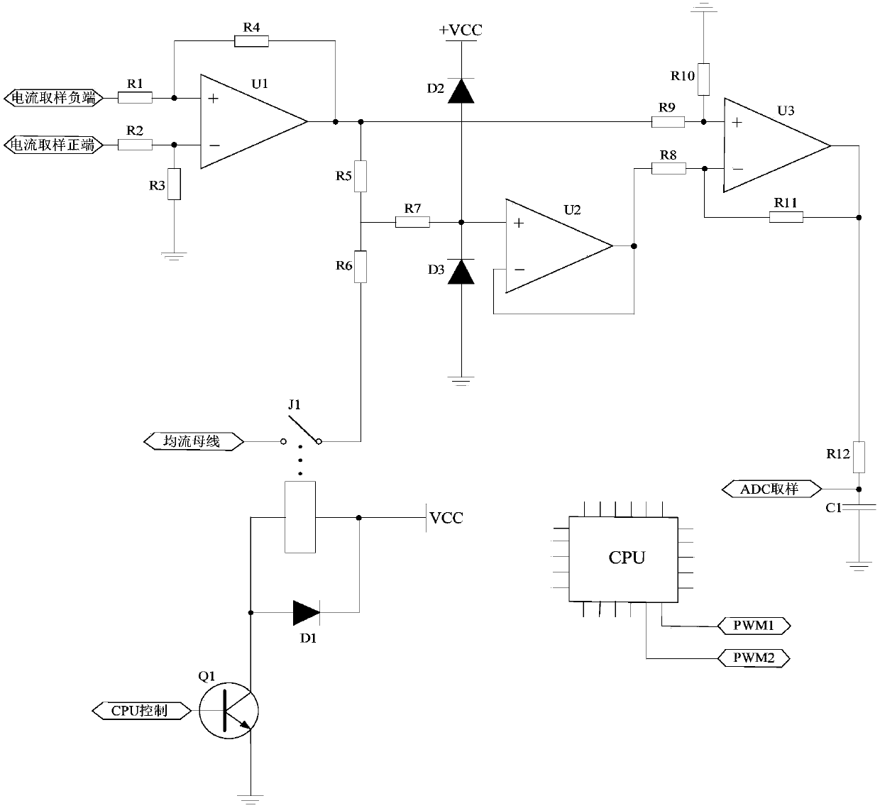
The invention belongs to the technical field of switching power supplies, and relates to a multi-machine parallel current sharing circuit and a digital control switching power supply. The multi-machine parallel current sharing circuit comprises a first differential mode amplifier circuit, a parallel operation current sharing bus circuit, a protection circuit, a second differential mode amplifier circuit, an RC filter circuit and a processor. The first differential mode amplifier circuit is electrically connected with the parallel operation current sharing bus circuit, the first differential mode amplifier circuit is also electrically connected with the second differential mode amplifier circuit, and the parallel operation current sharing bus circuit is electrically connected with the protection circuit. The parallel operation current sharing bus circuit is also connected with the processor, the second differential mode amplifier circuit is electrically connected with the RC filter circuit, and the RC filter circuit is electrically connected with the processor. The multi-machine parallel current sharing circuit has the advantages of high universality, low cost and the like.

Description

Technical field [0001] This application belongs to the technical field of switching power supplies, and relates to multi-machine parallel current sharing circuits and digitally controlled switching power supplies. Background technique [0002] At present, in the need to use switching power supply and airport, the switching power supply used must have parallel current sharing circuit technology. The commonly used technology is to use dedicated current sharing chips, such as UC1902 series chips. Generally speaking, the use of dedicated current-sharing chips has disadvantages such as high cost, difficult to purchase, and inflexible use. Or other types of current sharing circuit technology used in switching power supplies in analog control mode. [0003] In the process of studying the present application, the inventor found that the switching power supply in the prior art either uses a dedicated current-sharing chip to perform multi-machine parallel current-sharing control, which has...

Claims


Application Information

Patent Timeline
Patent Type & Authority Applications(China)
IPC IPC(8): H02M3/04H02H7/12
CPCH02H7/1213H02M3/04H02M1/0012
Inventor 钟延煌蔡智勇
Owner 深圳市英合科技有限公司
Learn More