
Five-axis stamping robot

A technology of a robot and a stamping mechanism, which is applied in the field of stamping mechanisms, can solve the problem of inability to guarantee the rotation of the servo motor. The first sliding device slides up and down. The first sliding device is equipped with a second rotary servo motor along the front and rear directions. The rotating part of the second rotary servo motor is connected to the cross arm. The second sliding device, the mechanical arm is installed in the chute and the mechanical arm is connected to the second sliding device, the lower side of the end of the mechanical arm passes through the third rotation servo and other issues to achieve the effect of ensuring the stamping effect

Active Publication Date: 2020-03-17
HARBIN UNIV
View PDF9 Cites 3 Cited by
  • Summary
  • Abstract
  • Description
  • Claims
  • Application Information

AI Technical Summary

Problems solved by technology

[0002] For example, the publication number CN206104732U discloses a five-axis stamping robot, including a machine base, a first rotary servo motor is arranged vertically on the machine base, a base is set on the rotating part of the first rotary servo motor, and a first column is set on the base , the first column is provided with a first sliding device that can slide up and down, the first sliding device is provided with a second rotary servo motor along the front and rear directions, the rotating part of the second rotary servo motor is connected to the cross arm, and a chute is provided on the cross arm, A second sliding device that can slide back and forth is provided on the side of the cross arm, a mechanical arm is arranged in the chute and connected to the second sliding device, and a stamping manipulator is rotatably provided on the lower side of the end of the mechanical arm through a third rotary servo motor; this practical The disadvantage of the new type is that it cannot guarantee that when stamping any position, there is always a corresponding vertical stamping force above the stamping die.

Method used


Image

  • Five-axis stamping robot
  • Five-axis stamping robot
  • Five-axis stamping robot

Examples


specific Embodiment approach 1

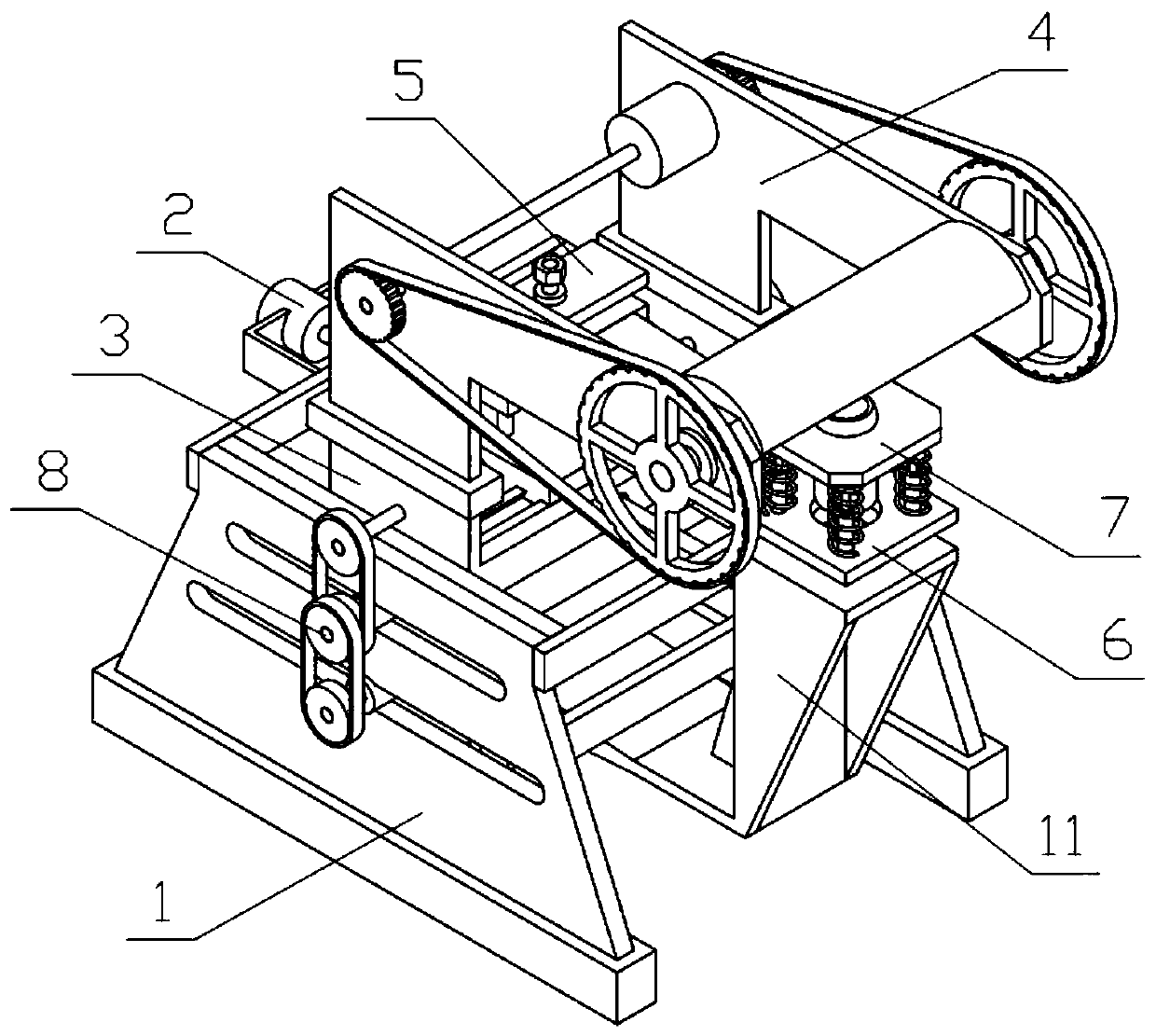
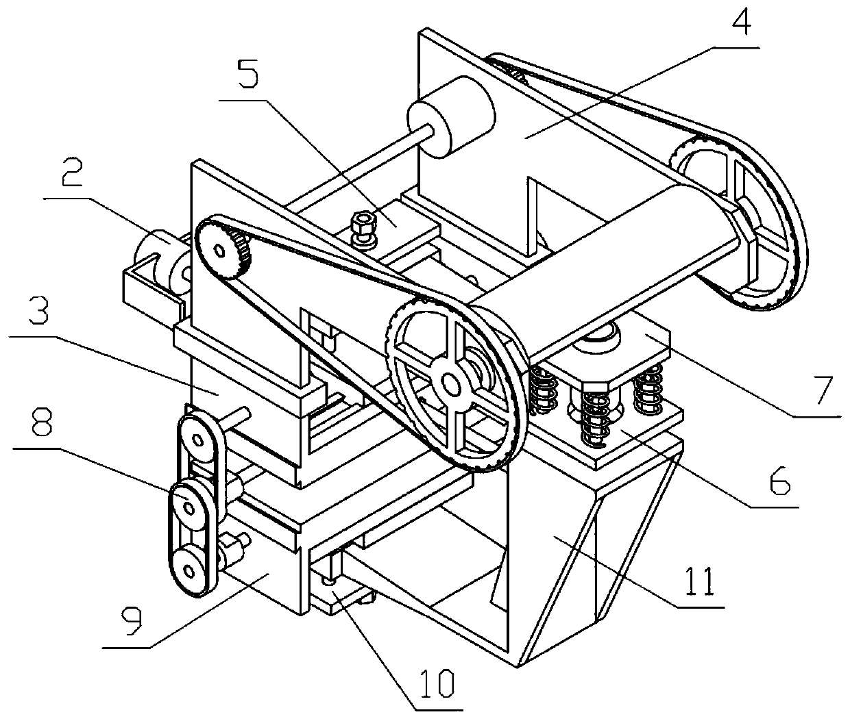
[0035] Combine below Figure 1-12Describe this embodiment, a five-axis stamping robot, including a device bracket 1, a moving motor I2, a sliding bracket I3, a stamping mechanism 4, a height bracket I5, a mold support plate 6, a stamping die 7, a moving mechanism 8, a sliding bracket II9, The height bracket II10 and the stamping chassis 11, the device bracket 1 is fixedly connected with the mobile motor I2, the device bracket 1 is slidably connected with the sliding bracket I3, and the sliding bracket I3 is connected to the output shaft of the mobile motor I2 through threads, and the sliding bracket The stamping mechanism 4 is fixedly connected to the Ⅰ3, the height bracket Ⅰ5 is slidably connected to the sliding bracket Ⅰ3, the mold support plate 6 is fixedly connected to the height bracket Ⅰ5, the stamping die 7 is slidingly connected to the mold support plate 6, the stamping die 7 and the mold support Compression springs are fixedly connected between the plates 6, the upper...

specific Embodiment approach 2

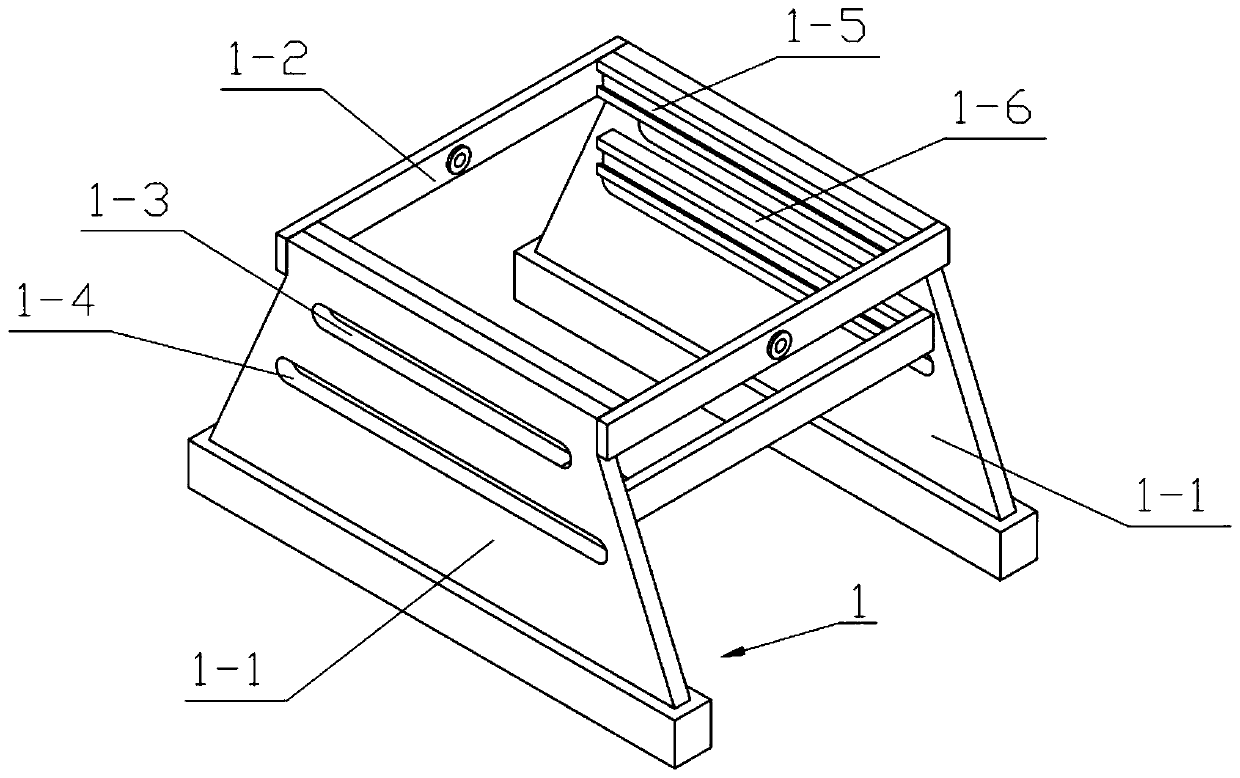
[0037] Combine below Figure 1-12 Describe this embodiment, this embodiment will further explain the first embodiment, the device bracket 1 includes a support plate 1-1, a connecting plate 1-2, a sliding waist hole I1-3, a sliding waist hole II1-4, and a sliding track I1 -5 and sliding track II 1-6, two support plates 1-1 are provided, and a connecting plate 1-2 is fixedly connected in the middle of the two support plates 1-1, and a sliding track is provided on the two support plates 1-1. The waist hole I1-3 and the sliding waist hole II1-4 are fixedly connected with the sliding track I1-5 and the sliding track II1-6 on the inner sides of the two support plates 1-1.

specific Embodiment approach 3

[0039] Combine below Figure 1-12 Describe this embodiment, this embodiment will further explain the second embodiment, the sliding bracket I3 includes a sliding bottom plate I3-1, a sliding track III3-2 and a side plate I3-3, and the sliding bottom plate I3-1 is slidably connected to two Between the sliding tracks Ⅰ1-5, the sliding bottom plate Ⅰ3-1 is fixedly connected with the sliding track Ⅲ3-2, both sides of the sliding bottom plate Ⅰ3-1 are fixedly connected with the side plates Ⅰ3-3, and the mobile motor Ⅰ2 is fixedly connected with the connecting plate 1 On -2, the sliding bottom plate I3-1 is connected to the output shaft of the mobile motor I2 through threads.


PUM


Abstract

The invention relates to a stamping mechanism, in particular to a five-axis stamping robot. The five-axis stamping robot comprises a device support, a moving motor I, a sliding support I, a stamping mechanism, a height support I, a die supporting plate, a stamping die, a moving mechanism, a sliding support II, a height support II and a stamping bottom frame. The sliding support I, the stamping mechanism, the height support I, the die supporting plate, the stamping die, the moving mechanism, the sliding support II, the height support II and the stamping bottom frame can be driven by the movingmotor I to conduct transverse movement, the stamping position of the stamping die on the X axis in the plane is adjusted, the stamping position of the stamping die on the Y axis in the plane is adjusted by the moving mechanism, and therefore the situation that the stamping mechanism is arranged above the stamping die all the time when the stamping operation is conducted at the random position is guaranteed, the stamping mechanism generates the corresponding perpendicular stamping force, and the stamping effect is guaranteed. In addition, the die supporting plate and the stamping bottom frame move together, and therefore the stamping position is guaranteed.

Description

technical field [0001] The invention relates to a stamping mechanism, more specifically a five-axis stamping robot. Background technique [0002] For example, the publication number CN206104732U discloses a five-axis punching robot, including a machine base, a first rotary servo motor is arranged vertically on the machine base, a base is set on the rotating part of the first rotary servo motor, and a first column is set on the base , the first column is provided with a first sliding device that can slide up and down, the first sliding device is provided with a second rotary servo motor along the front and rear directions, the rotating part of the second rotary servo motor is connected to the cross arm, and a chute is provided on the cross arm, A second sliding device that can slide back and forth is provided on the side of the cross arm, a mechanical arm is installed in the chute and connected to the second sliding device, and the punching manipulator is rotatably provided o...

Claims


Application Information

Patent Timeline
Patent Type & Authority Applications(China)
IPC IPC(8): B21D22/02B21D37/12
CPCB21D22/02B21D37/12
Inventor 兰文宝车畅
Owner HARBIN UNIV
Learn More