Hydraulic cylinder and tunnel boring machine

A technology of hydraulic cylinders and cylinders, applied in tunnels, fluid pressure actuation devices, mining equipment, etc., can solve the problems of low degree of freedom of the sensor body and the long time required for sensor replacement.

Active Publication Date: 2020-03-17
KOMATSU LTD
View PDF2 Cites 0 Cited by
  • Summary
  • Abstract
  • Description
  • Claims
  • Application Information

AI Technical Summary

Problems solved by technology

[0003] In the structure disclosed in the above publication, the degree of freedom in the arrangement of the sensor body is low, and the sensor body has to be installed at a position where maintenance and maintenance are difficult.
In such a case, when the magnetostrictive displacement sensor fails, there is concern that sensor replacement will take a long time

Method used


Image

  • Hydraulic cylinder and tunnel boring machine
  • Hydraulic cylinder and tunnel boring machine
  • Hydraulic cylinder and tunnel boring machine

Examples


Embodiment Construction

[0012] Hereinafter, embodiments of the present invention will be described based on the drawings. It should be noted that, in the specification and the drawings, the same constituent elements or corresponding constituent elements are assigned the same reference numerals, and repeated descriptions are not repeated. In addition, in the drawings, the structure may be omitted or simplified for convenience of description.

[0013] (Structure of tunnel boring machine)

[0014] First, the structure of a tunnel boring machine to which the hydraulic cylinder of the present invention can be applied will be described.

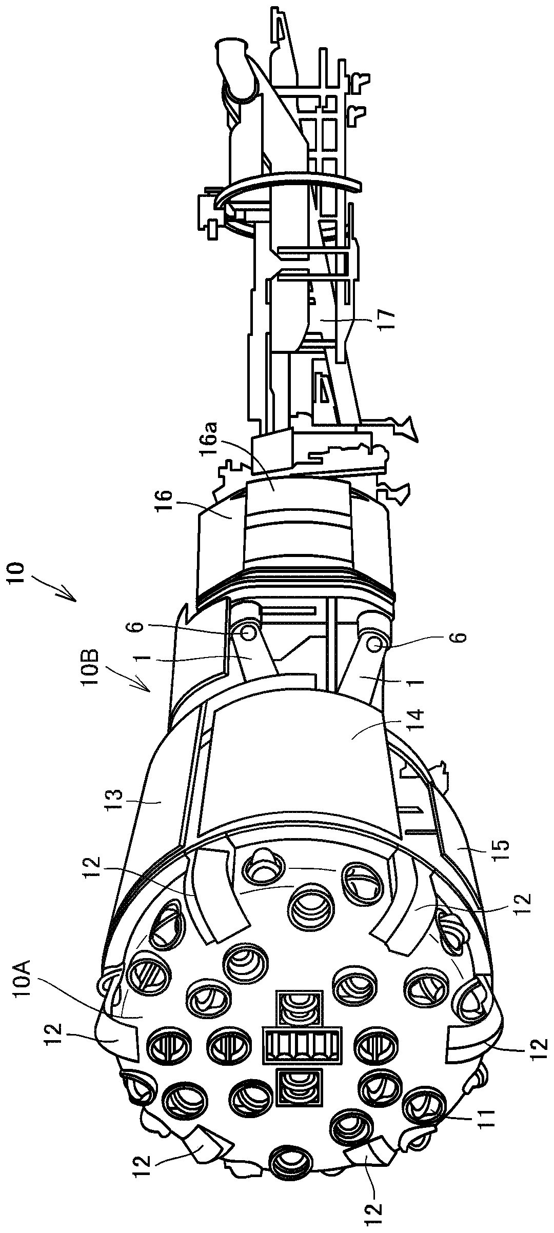
[0015] figure 1 It is a perspective view schematically showing the structure of the tunnel boring machine 10 in one embodiment. Such as figure 1 As shown, the tunnel boring machine 10 excavates underground by rotating the cutter head 10A in a state supported by the main shoe 16 (a shoe) on the tunnel wall in the ground. The tunnel boring machine 10 has a cutter head ...


PUM


Abstract

The invention provides a hydraulic cylinder and a tunnel boring machine which are high in degree of freedom of arrangement of sensors and easy to maintain. The cylinder tube (2) has a tube section (2a). The piston rod (4) slides inside the cylinder part (2a). The sensor device (6) has a sensor main body (6a) attached to the cylinder tube (2), a magnetostriction wire (6b) connected to the sensor main body (6a), and a magnet (6c) attached to the piston rod (4) inside the tube section (2a) and applying a magnetic field to the magnetostriction wire (6b). The magnetostriction line (6b) includes a first portion (6ba) extending in an axial direction (A) of the piston rod (4), and a second portion (6bb) extending offset from the axial direction (A) to connect the first portion (6ba) to the sensorbody (6a).

Description

technical field [0001] The invention relates to a hydraulic cylinder and a tunnel boring machine. Background technique [0002] Hydraulic cylinders (thrust hydraulic cylinders) of tunnel boring machines operate in dusty and flooded environments. Therefore, as the stroke sensor of the hydraulic cylinder, a magnetostrictive displacement sensor in which all sensors can be housed in the casing of the hydraulic cylinder is used. Such a hydraulic cylinder is disclosed, for example, in JP-A-2015-31298. [0003] In the configuration disclosed in the above publication, the degree of freedom in arrangement of the sensor body is low, and the sensor body has to be attached to a location where maintenance and maintenance are difficult. In such a case, when the magnetostrictive displacement sensor fails, there is a concern that sensor replacement will take a long time. Contents of the invention [0004] An object of the present invention is to provide a hydraulic cylinder and a tunne...

Claims


Application Information

Patent Timeline
IPC IPC(8): F15B15/14F15B15/28E21D9/00
CPCF15B15/14F15B15/2861E21D9/00
Inventor 荒川拓仓本丰司关山直树
Owner KOMATSU LTD
Why Eureka
Try Eureka