Iron-absorbing swing arm tension detection device

A technology of tension detection and air device, which is applied in the field of special testing devices for textile machinery components, can solve the problems of high operating intensity, waste of resources, and low efficiency of operators, and achieve the reduction of operating intensity and clamping operation requirements, avoiding waste of resources, The effect of preventing product costs

Active Publication Date: 2021-03-12
常熟纺织机械厂有限公司
View PDF16 Cites 0 Cited by
  • Summary
  • Abstract
  • Description
  • Claims
  • Application Information

AI Technical Summary

Problems solved by technology

Although this detection method can measure the maximum tensile force that the iron-absorbing swing arm can withstand, there are the following technical problems: First, because the clamping method is inconsistent with the actual force-bearing mode of the iron-absorbing swing arm, it is difficult to guarantee the test effect; Its two, because each test all needs at first by means of special fixtures to fix the iron-absorbing swing arm, and then supply it to the tensile testing machine for testing, so on the one hand, the efficiency is low, on the other hand, the operator's work intensity is large, and it is harmful to the operator. The operation requirements are relatively high; third, because the clamping position of the iron-absorbing swing arm cannot be objectively consistent during the clamping before each test, resulting in deviations in the test results; fourth, because the test method is destructive After the test is completed, the suction arm swing arm can only be scrapped, which not only causes waste of resources, but also is not conducive to product cost control
As far as the aforementioned iron-absorbing swing arm is concerned, the problem of how to correctly, efficiently and conveniently detect whether its pulling force is qualified has long plagued the industry and is expected to be solved, but it has not been found in the Chinese and foreign patents and non-patent literature published so far. There are technical revelations that can be used for reference. For this reason, the applicant has made a positive and beneficial design and it is proved to be feasible by computer simulation tests under the security measures.

Method used


Image

  • Iron-absorbing swing arm tension detection device
  • Iron-absorbing swing arm tension detection device

Examples


Embodiment Construction

[0020] In order to be able to understand the technical essence and beneficial effects of the present invention more clearly, the applicant will describe in detail below by way of examples, but the description of the examples is not intended to limit the solution of the present invention. Equivalent transformations that are only formal but not substantial should be regarded as the scope of the technical solutions of the present invention.

[0021] In the following description, all concepts related to the directionality or orientation of up, down, left, right, front and rear are referred to as figure 1 The location state is taken as an example, and therefore cannot be understood as a special limitation on the technical solution provided by the present invention.

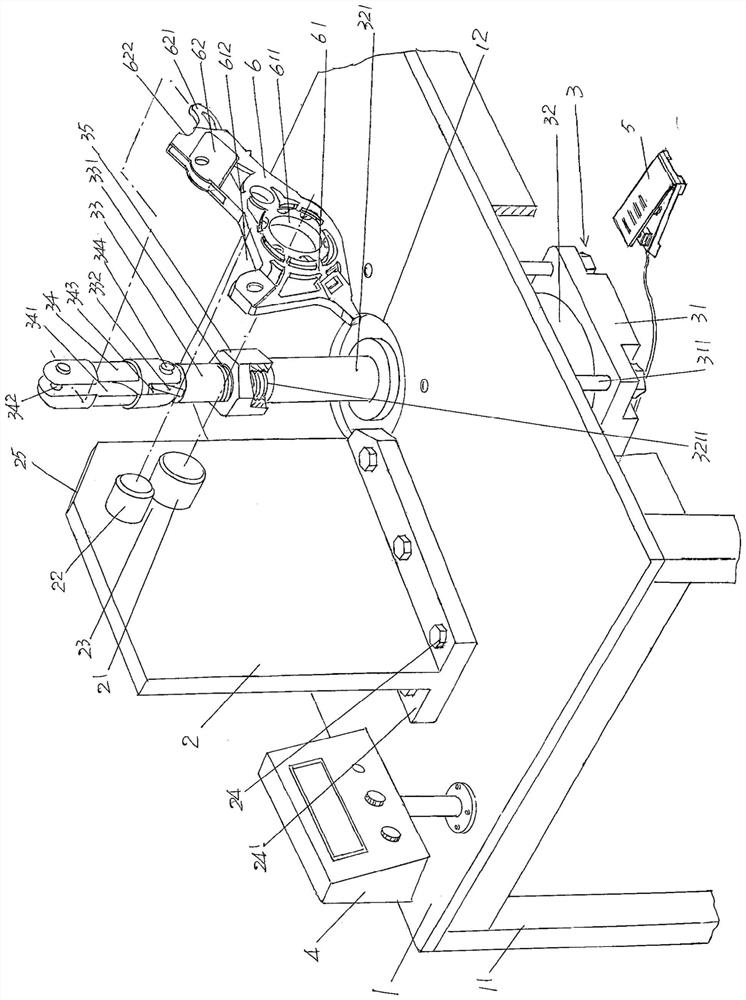
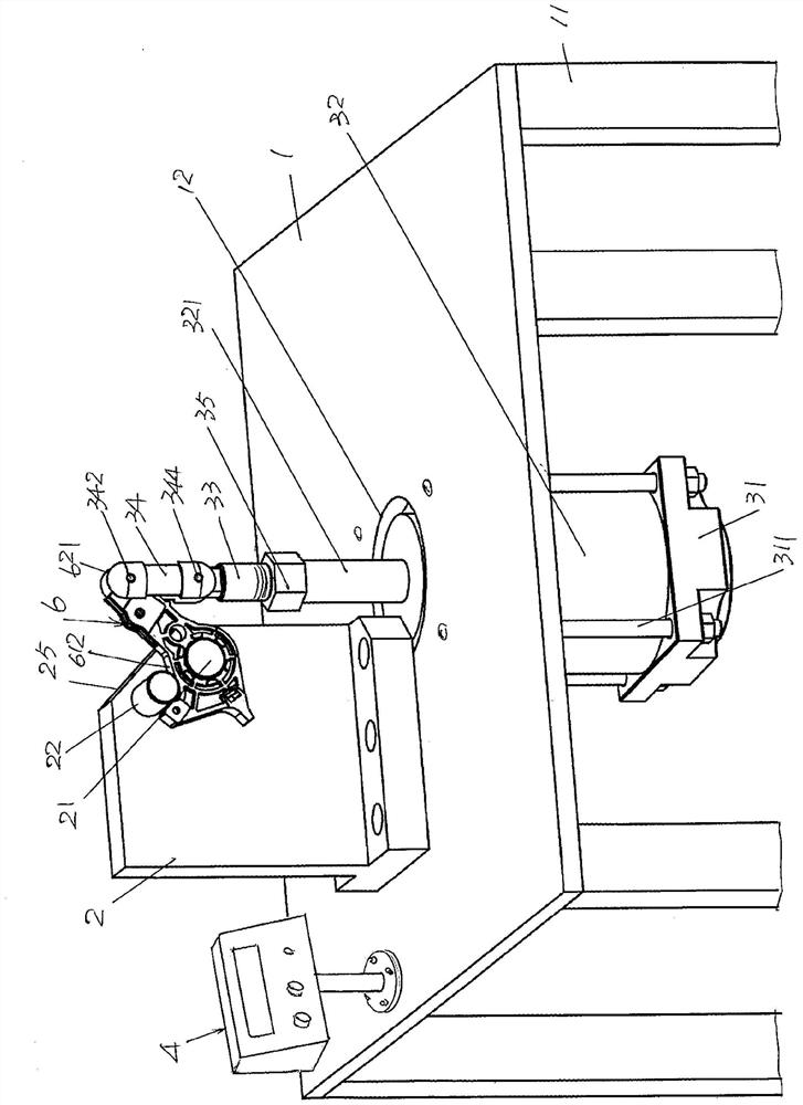
[0022] See figure 1 , shows a test bench 1; shows a swing arm temporarily hanging bracket 2 and a pneumatic swing arm pulling mechanism 3, the swing arm temporarily hanging bracket 2 is fixed on the aforementioned tes...


PUM


Abstract

The invention discloses a magnet swing arm tension detection device, and belongs to the technical field of special testing devices for textile machine components. The device comprises a test board, aswing arm temporary hanging support and a pneumatic swing arm pulling mechanism. The swing arm temporary hanging support is fixedly arranged on the test board; the right upper part of the swing arm temporary hanging support is fixedly provided with a swing arm temporary hanging column and a swing arm palm concave cavity limiting column; the swing arm palm concave cavity limiting column correspondsto the upper portion of the swing arm palm temporary hanging column, and the space between the swing arm palm concave cavity limiting column and the swing arm palm temporary hanging column forms a swing arm shaft hole wall receding cavity; the pneumatic swing arm pulling mechanism is arranged on the test board and corresponds to the right side of the swing arm temporary hanging support; and the pneumatic swing arm pulling mechanism is connected with a gas production device. The test effect is ensured; the overall structure is concise; the clamping time is shortened and the detection efficiency is improved; the operation intensity of an operator and the clamping operation requirement can be remarkably reduced; deviation of a test result is avoided; and cost is reduced.

Description

technical field [0001] The invention belongs to the technical field of special testing devices for textile components, and in particular relates to a tension detection device for an iron-absorbing swing arm. Background technique [0002] The iron suction swing arm mentioned above is an important part in the structural system of the signal device on the dobby, and the dobby is matched with the loom to convert the signal of the fabric pattern into the opening action and drive the weaving. The heald frame of the machine is used as the opening part of the loom for lifting the heald up and down. Because the specific function of the iron suction swing arm can be provided by "a rotary dobby mechanism for a loom" recommended by FR-2540524, "rotary dobby mechanism and a loom equipped with such a dobby mechanism" introduced by CN1057352C and CN102400257B The "Rotary Dobby Opening Mechanism" etc. has been fully understood by reading, so the applicant will not repeat it. [0003] Beca...

Claims


Application Information

Patent Timeline
Patent Type & Authority Patents(China)
IPC IPC(8): G01M13/00G01L5/00
CPCG01L5/0033G01M13/00
Inventor 彭晓虹曹丽忠卫明陶煜陆国平
Owner 常熟纺织机械厂有限公司
Why Eureka
Try Eureka