Accelerometer core butting structure and butting method

A technology of accelerometer and watch movement, applied in speed/acceleration/shock measurement, detailed information of speed/acceleration/electric shock meter, measuring device, etc. It can solve the problem of unquantifiable docking force, damaged docking of watch movement, and uneven force application and other problems, to achieve the effect of increasing the adjustable range, increasing the stepping accuracy, and compact structure

Pending Publication Date: 2020-03-17
XIAN AEROSPACE PRECISION ELECTROMECHANICAL INST
View PDF9 Cites 0 Cited by
  • Summary
  • Abstract
  • Description
  • Claims
  • Application Information

AI Technical Summary

Problems solved by technology

[0005] The main purpose of the present invention is to solve the technical problem that the docking force cannot be quantified when the watch movement is docked in the prior art, and the butt force is too large and the force is uneven, resulting in damage to the watch movement or inaccurate docking. Meter core docking structure and docking method

Method used


Image

  • Accelerometer core butting structure and butting method
  • Accelerometer core butting structure and butting method
  • Accelerometer core butting structure and butting method

Examples


Embodiment 1

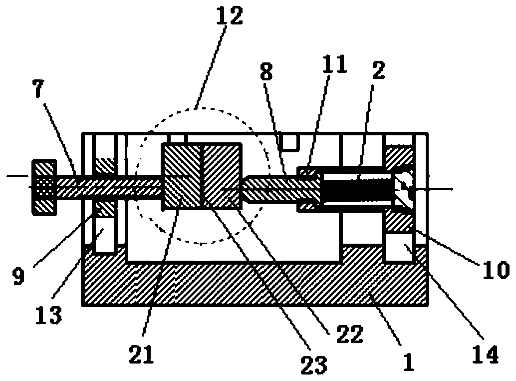
[0040] Such as image 3 and Figure 4 As shown, a docking structure of an accelerometer watch core includes a first axial push rod 7, a second axial push rod 8, a first radial push plate 3, a second radial push plate 4, a first radial adjustment The rod 5 and the second radial adjustment rod 6; the docking base 1 is provided with a first sliding cavity 13 and a second sliding cavity 14 along the vertical direction.

[0041]The first axial push rod 7 passes through the side wall of the docking base 1 and is arranged in the axial direction of the watch movement 12 to be installed. The first axial push rod 7 is covered with a first mounting seat 9, and the first mounting seat 9 is installed on the docking In the first sliding cavity 13 in the base 1, the first mounting seat 9 is screwed with the first axial push rod 7; the second axial push rod 8 is coaxially arranged with the first axial push rod 7, and the second axial The ejector rod 8 is installed in the docking base 1 thro...

Embodiment 2

[0043] Such as Figure 4 and Figure 5 As shown, a docking structure of an accelerometer watch core includes a first axial push rod 7, a second axial push rod 8, a first radial push plate 3, a second radial push plate 4, a first radial adjustment The rod 5 and the second radial adjustment rod 6; the docking base 1 is provided with a first sliding cavity 13 and a second sliding cavity 14 along the vertical direction.

[0044] The first axial push rod 7 passes through the side wall of the docking base 1 and is arranged in the axial direction of the watch movement 12 to be installed. The first axial push rod 7 is covered with a first mounting seat 9, and the first mounting seat 9 is installed on the docking In the first sliding cavity 13 in the base 1 , the first installation seat 9 is threadedly engaged with the first axial push rod 7 . The first mounting seat 9 is installed in the first sliding cavity 13, a second spring 15 is provided between the first mounting seat 9 and th...


PUM


Abstract

The invention belongs to an accelerometer mounting structure and mounting method, aims to solve the technical problems of damage to the core or inaccurate butting caused by excessively butting force or uneven force and the fact that the butting force cannot be quantified when the core is butted, and provides an accelerometer core butting structure and butting method. Flexible axial butting betweena first axial ejector rod and a second axial ejector rod is achieved through the butting structure by means of a first spring, and a first radial adjusting rod and a second radial adjusting rod are matched with a first radial push plate and a second radial push plate respectively to conduct radial butting on the accelerometer core. The butting method comprises the following steps: firstly, the first radial adjusting rod and the second radial adjusting rod are used, a first radial push plate and a second radial push plate are close to each other, the core is placed between the two radial pushplates, then the core is axially positioned and radially adjusted again, the mass center of the core to be installed, the first axial ejector rod and the second axial ejector rod are located on the same straight line and then glue pouring packaging is carried out to complete butting.

Description

technical field [0001] The invention belongs to an accelerometer installation structure and an installation method, in particular to an accelerometer watch core docking structure and a docking method. Background technique [0002] The accelerometer is an inertial navigation system that uses Newton's second law to measure acceleration. It is widely used in various aviation systems and is one of the core components of the navigation system. The docking of the accelerometer watch core refers to overcoming the repulsion of the upper and lower torque devices, and precisely connecting the upper and lower torque devices with the pendulum assembly through external forces. The coaxiality of the three needs to strictly meet the technical requirements. Docking is a key process of accelerometer assembly, and the accuracy of the docking directly determines the range of the accelerometer and the subsequent test accuracy. [0003] The current leveling principle of accelerometer core docki...

Claims


Application Information

Patent Timeline
Patent Type & Authority Applications(China)
IPC IPC(8): G01P1/00
CPCG01P1/00
Inventor 张阳
Owner XIAN AEROSPACE PRECISION ELECTROMECHANICAL INST
Why Eureka
Try Eureka