Double-station pyrography machine
A heat press machine and double-station technology, which is applied to printing machines, rotary printing machines, printing, etc., can solve problems such as heat press errors, reduce work efficiency, and affect work, so as to facilitate leveling, improve work efficiency, and improve quality Effect
- Summary
- Abstract
- Description
- Claims
- Application Information
AI Technical Summary
Problems solved by technology
Method used
Image
Examples
Embodiment 1
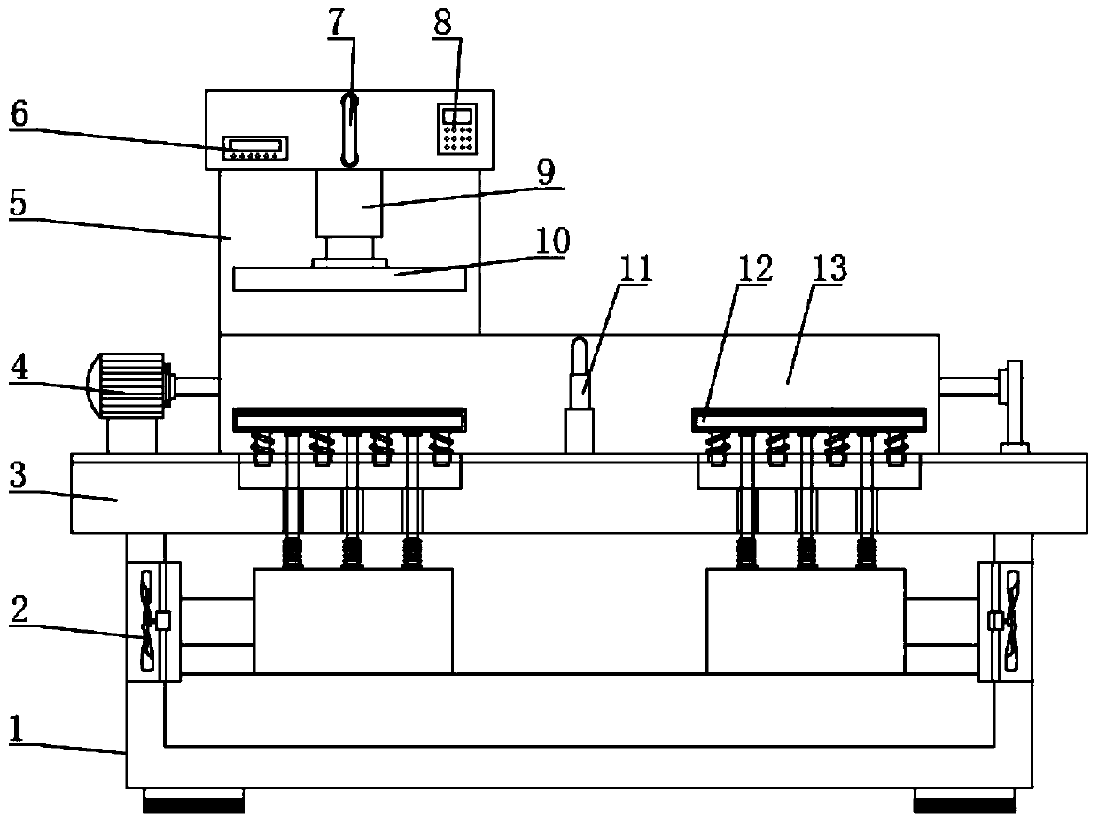
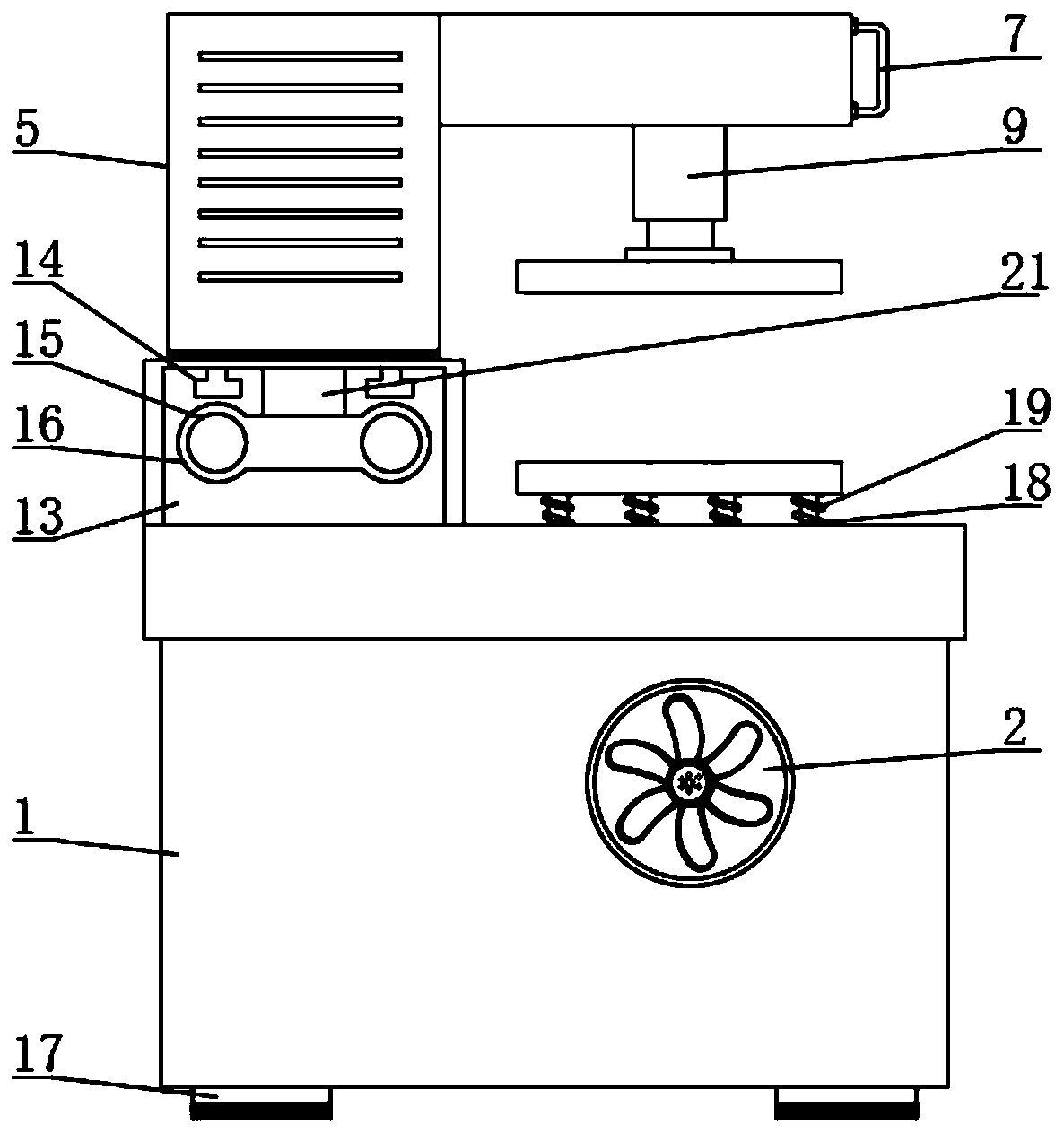
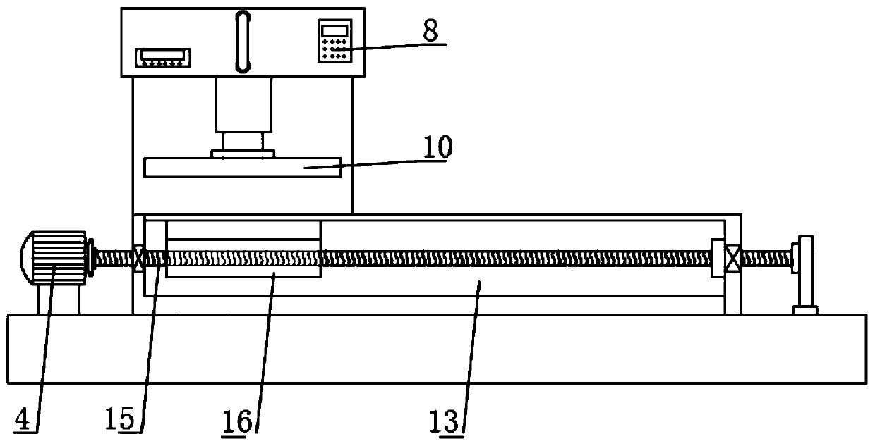
[0036] Embodiment one, with reference to Figure 1-4 , a double-station heat press machine, including a heat press machine body 1, a worktable 3 is installed on the top of the heat press machine body 1, and a mobile platform 13 is installed on one side of the top of the workbench 3, and a heat press machine is installed on the top of the mobile platform 13 Mechanism 5, a screw rod 15 is installed horizontally inside the mobile table 13, and the surface of the screw rod 15 is sleeved with a threaded sleeve 16, one end of the screw sleeve 16 is fixed to the mounting plate 23, and the top surface of the mounting plate 23 is equipped with a connecting piece 21, the connecting piece 21 One end runs through the slideway 22 on the top of the mobile table 13 and is fixed to the bottom of the heat transfer mechanism 5. The inside of the mobile table 13 is located on the side of the screw rod 15. A slide rod 25 is installed, and the surface of the slide rod 25 is sleeved with a sliding s...
Embodiment 2
[0038] Embodiment two, refer to figure 1 with figure 2, the top surface of the workbench 3 is equipped with a lower pressure plate 12, two lower pressure plates 12 are arranged, and the two lower pressure plates 12 are installed symmetrically about the center line of the workbench 3, the top surface of the lower pressure plate 12 is provided with a non-woven fabric 20, the lower pressure plate 12 The top is provided with a through hole 26, the lower platen 12 is provided with a cavity 27, and the bottom end of the lower platen 12 is provided with a pipeline 29, the pipeline 29 is connected to the transition bellows 31 through the hose 30 at the bottom, and one end of the transition bellows 31 is connected to the transition bellows 31 through the pipeline 29. The exhaust fan 2 on the surface of the heat press machine body 1 is connected.
[0039] By setting the exhaust fan 2, when the staff lays the cloth on the surface of the lower pressing plate 12, the staff starts the exh...
Embodiment 3
[0040] Embodiment three, refer to figure 1 with Figure 5 , the bottom end of the lower platen 12 is equipped with a buffer column 19, and the surface of the buffer column 19 is sleeved with a buffer spring 18, and one end of the buffer column 19 extends into the buffer cavity 28 provided inside the workbench 3, and there are multiple buffer columns 19, and A plurality of buffer posts 19 are equidistantly installed on the bottom surface of the lower pressing plate 12 .
[0041] By arranging the buffer column 19 and the buffer spring 18, through the cooperation of the buffer column 19 and the buffer spring 18, it is convenient to make the upper pressing plate 10 buffer the pressure of the lower pressing plate 12 during work, thereby preventing the gap between the lower pressing plate 12 and the upper pressing plate 10. Hard contact occurs to prevent damage to the cloth.
PUM
 Abstract
Description
Claims
Application Information
 - R&D
- Intellectual Property
- Life Sciences
- Materials
- Tech Scout
- Unparalleled Data Quality
- Higher Quality Content
- 60% Fewer Hallucinations
Browse by: Latest US Patents, China's latest patents, Technical Efficacy Thesaurus, Application Domain, Technology Topic, Popular Technical Reports.
© 2025 PatSnap. All rights reserved.Legal|Privacy policy|Modern Slavery Act Transparency Statement|Sitemap|About US| Contact US: help@patsnap.com


