Punching device for building fastener production

A technology for punching devices and fasteners, which is applied in the direction of stripping devices, metal processing equipment, manufacturing tools, etc., can solve problems such as not easy to fall, affect the continuity of punching holes, reduce the production efficiency of building fasteners, etc., and achieve a smooth downward movement Effect

Inactive Publication Date: 2020-03-24
RIZHAO WEIYE TOOL
View PDF7 Cites 2 Cited by
  • Summary
  • Abstract
  • Description
  • Claims
  • Application Information

AI Technical Summary

Problems solved by technology

[0003] At present, most of the existing punching devices for the production of building fasteners on the market have the following deficiencies during use: after punching, sometimes, the punched waste is easy to be inserted into the punching head and is not easy to fall , the staff needs to dig it out before the next punching, the above-mentioned shortcomings affect the continuity of punching and reduce the production efficiency of construction fasteners

Method used


Image

  • Punching device for building fastener production
  • Punching device for building fastener production
  • Punching device for building fastener production

Examples


Embodiment 1

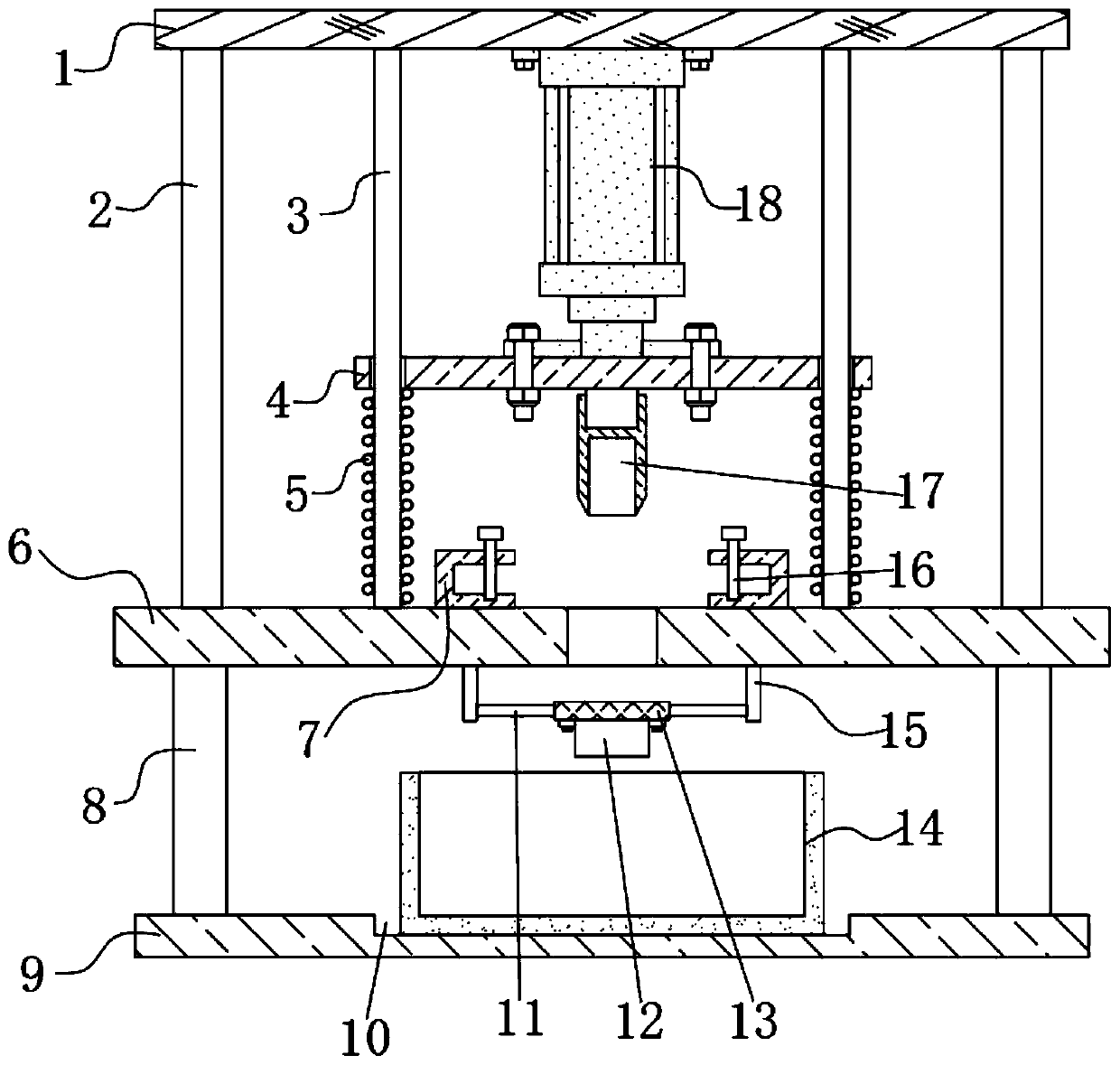
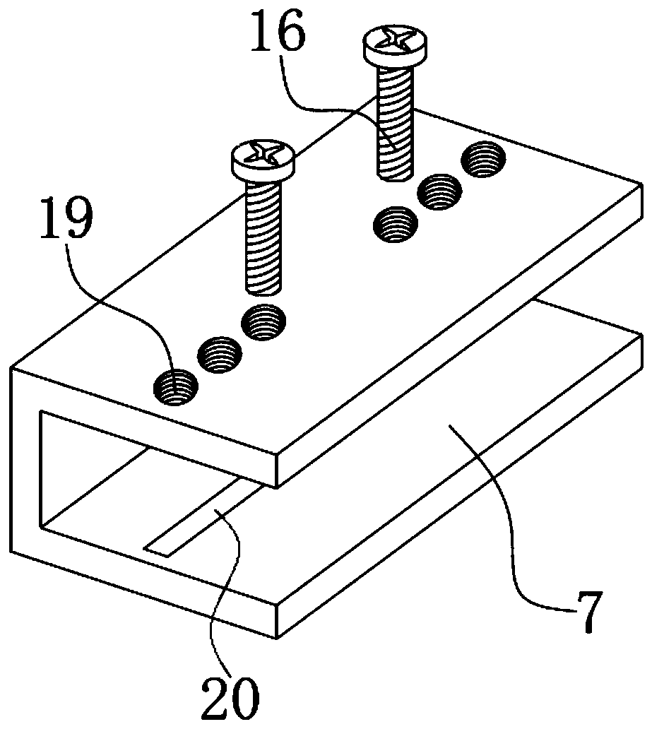
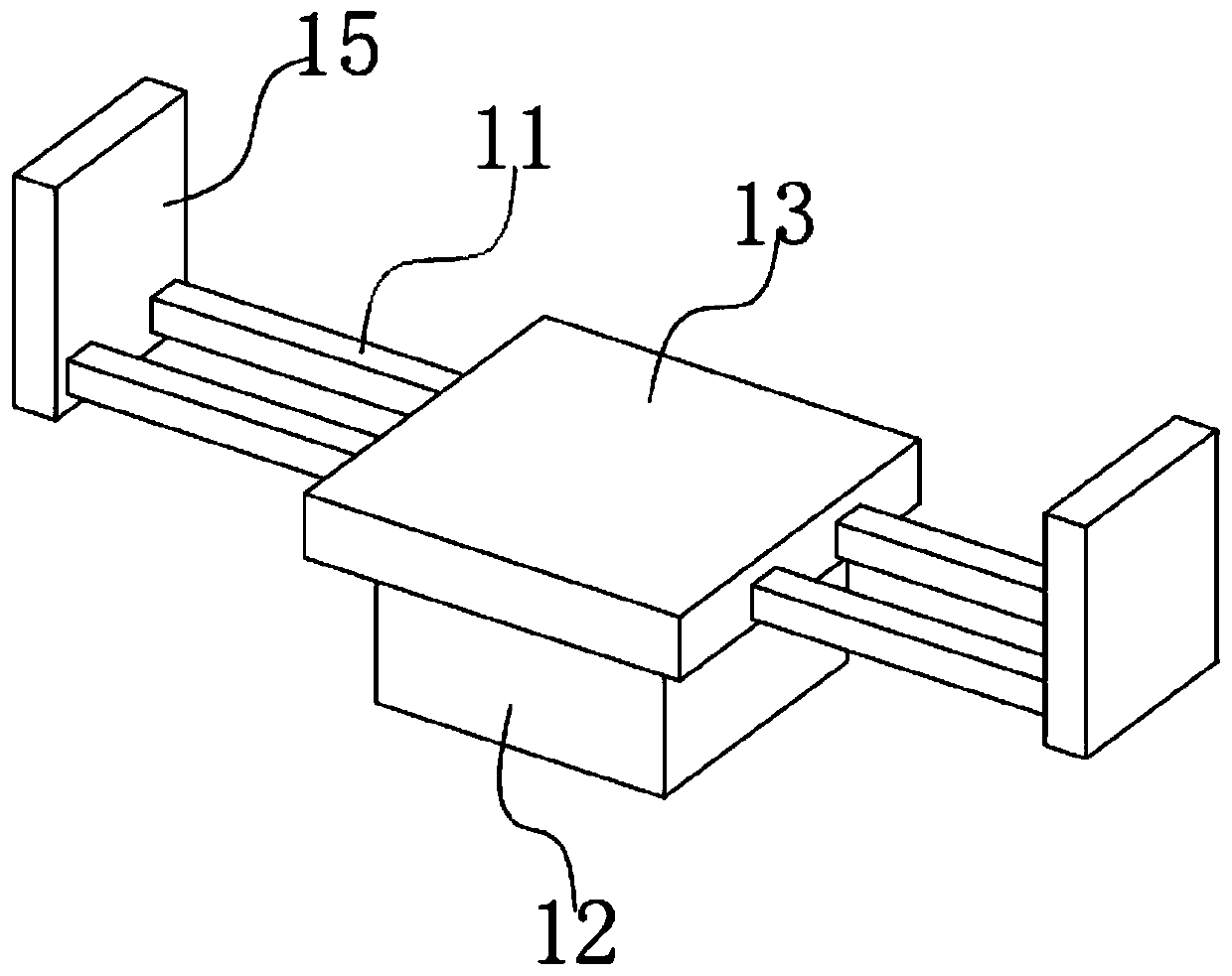
[0025] refer to Figure 1-3 , a punching device for the production of building fasteners, including a platen 6 and a punching mechanism, the top outer wall of the platen 6 is provided with a blanking hole, and the top outer wall of the platen 6 is fixed with two U-shaped seats 7 by bolts, There are two sets of threaded holes 19 on the top of the U-shaped seat 7, and the screw rods 16 are inserted into the internal threads of the two sets of threaded holes 19. Before punching, insert the two ends of the sheet into the two U-shaped seats 7 respectively. According to the size of the sheet, insert the screw 16 into the threaded hole 19 at a suitable position, and use the screw 16 to press the sheet tightly, thus completing the fixing of the sheet, so that the subsequent more accurate punching, the platen The outer wall of the bottom of 6 is welded with two vertical plates 15, and the outer wall of the opposite side of the two vertical plates 15 is welded with two cross bars 11, an...

Embodiment 2

[0034] refer to Figure 4 , a punching device for the production of building fasteners. Compared with Embodiment 1, the main difference of this embodiment is that in this embodiment, the inner wall of the bottom of the groove 10 is welded with a plurality of pads 21 with a semicircular end structure.

[0035] Working principle: when in use, the pad 21 with a semicircular end surface structure can reduce the contact area with the bottom of the material receiving box 14, so that the staff can take out the material receiving box 14 more labor-saving in the later stage.


PUM


Abstract

The invention discloses a punching device for building fastener production. The punching device for building fastener production comprises a table plate and a punching mechanism, wherein a falling hole is formed in the outer wall of the top of the table plate; two U-shaped seats are fixed to the outer wall of the top of the table plate through bolts; two groups of thread holes are formed in the top of each U-shaped seat; screw rods are inserted and connected into the two groups of thread holes through internal threads; two vertical plates are fixedly connected to the outer wall of the bottom of the table plate; two cross rods are fixedly connected to the outer walls of the opposite sides of the two vertical plates; the same iron block plate is fixedly connected to the opposite ends of thefour cross rods; an electromagnet is fixed to the outer wall of the bottom of the iron block plate through a bolt; and the electromagnet is located below the falling hole. The invention discloses a punching device for building fastener production. The device is capable of assisting to discharge wastes punched off in a punching head after punching, and working personnel do not need to dig out the wastes which do not fall off in the punching head in the subsequent process, so that the punching continuity is ensured as much as possible.

Description

technical field [0001] The invention relates to the technical field of punching devices, in particular to a punching device for producing architectural fasteners. Background technique [0002] The construction fastener belongs to the field of construction machine parts. The production method of the building fastener includes the production method of the hot pressing process of the cover plate and the middle part. Wherein, the production method of cover plate is: after steel plate is gone out into blank through punching machine, blank is heated, punch out the shape of cover plate with punching machine, punch out bolt hole after workpiece cooling, then workpiece is put on the pouting machine, Respectively push up a protrusion on both sides of the outer side of the opening hole and then form it. In the above process of punching the workpiece, a punching device needs to be used. [0003] At present, most of the existing punching devices for the production of building fastener...

Claims


Application Information

Patent Timeline
Patent Type & Authority Applications(China)
IPC IPC(8): B21D28/26B21D28/04B21D45/06
CPCB21D28/04B21D28/26B21D45/06
Inventor 郑加华苗仲磊王晓王均龙
Owner RIZHAO WEIYE TOOL
Why Eureka
Try Eureka