Novel ceramic bending resistance degree testing device

A test device and bending-resistant technology, which is applied in the direction of measuring device, using a stable bending force to test the strength and strength characteristics of materials, can solve the problems of the influence of observation results and the influence of ceramic performance, and achieve centralized and effective cooling effect and cooling effect obvious effect

Inactive Publication Date: 2021-11-05
赵朋飞
View PDF0 Cites 0 Cited by
  • Summary
  • Abstract
  • Description
  • Claims
  • Application Information

AI Technical Summary

Problems solved by technology

[0002] New materials refer to newly developed or developing structural materials and functional materials with special properties. Structural materials mainly use their mechanical properties such as strength, toughness, hardness, and elasticity, such as new ceramic materials, amorphous Alloys (metallic glass), etc. Functional materials mainly use their functions and physical effects such as electricity, light, sound, magnetism, and heat. In recent years, new materials researched and developed in the world mainly include new metal materials, fine Ceramics and optical fibers, etc., in the process of making new ceramics, each finished sample must be tested for bending resistance and pressure resistance. The general testing device is to fix the ceramic sheet and then pressurize it to make it appear The target state, but the conventional extrusion will cause the friction between the ceramic and the extrusion to generate heat during the pressurization process, and the extra heat will affect the performance of the ceramic, so it will have a direct impact on the observation results. Therefore, a device is needed to simultaneously remove the friction between the extrusion surface and the ceramic surface and the heat generated by extrusion during the pressure and bending test of new ceramics

Method used


Image

  • Novel ceramic bending resistance degree testing device
  • Novel ceramic bending resistance degree testing device
  • Novel ceramic bending resistance degree testing device

Examples


Embodiment Construction

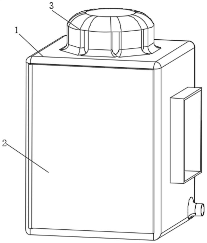
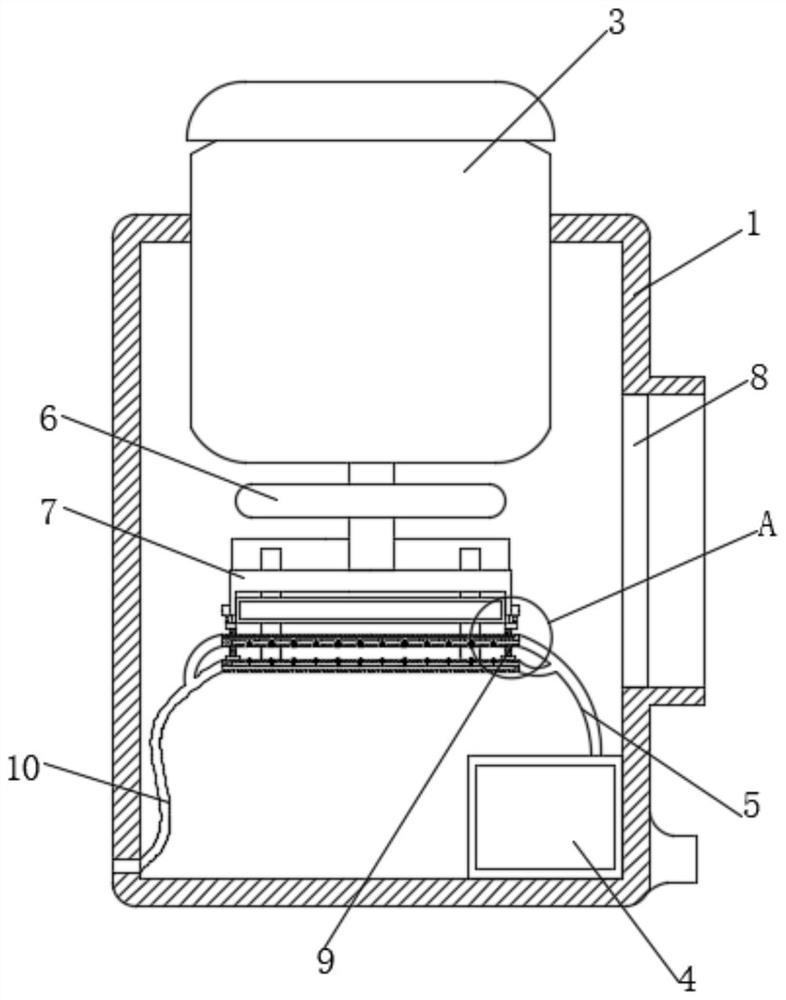
[0022] Such as Figure 1-6 As shown, the present invention provides a technical solution: a novel ceramic bending resistance test device, comprising a fixed box 1, an air inlet is provided at the bottom of the right side of the fixed box 1, and a cabinet door 2 is hinged on the front side of the fixed box 1 The upper side of the fixed box 1 is embedded with a built-in hydraulic machine 3, the lower side of the inner wall of the fixed box 1 is fixedly connected to the right side with a blower 4, the output end of the blower 4 is connected with a first air pipe 5, and the outer wall of the output rod of the hydraulic machine 3 is sleeved with a fixed Plate 6, the rear end of the first air pipe 5 is fixedly connected to the rear side of the inner wall of the fixed box 1, the lower end of the output rod of the hydraulic machine 3 is fixedly connected to the fixed frame 7, the right side of the fixed box 1 is provided with an observation window, and the inner wall of the observation...


PUM


Abstract

The invention relates to the technical field of new materials and discloses a novel ceramic bending resistance degree testing device. The device comprises a fixed box, wherein a cabinet door is hinged to the front side of the fixed box, a hydraulic machine is embedded and fixed to the upper side of the fixed box, and an air blower is fixedly connected to the right side of the lower side of the inner wall of the fixed box; a first air pipe is arranged at an output end of the air blower in a communicating mode, an outer wall of an output rod of the hydraulic machine is sleeved with a fixing plate, and a rear end of the first air pipe is fixedly connected to the rear side of the inner wall of the fixing box. When in use, air is drawn from an air inlet of the fixed box through the air blower, the air is conveyed into the right sides of a top extrusion plate and a bottom extrusion plate from an output end through a first air pipe, then the air is discharged from the left sides of the top extrusion plate and the bottom extrusion plate along a second air pipe, air circulation is completed, meanwhile, the top extrusion plate can move downwards to clamp a test object by rotating a threaded rod, and then a hydraulic machine is started to press a fixing frame downwards.

Description

technical field [0001] The invention relates to the technical field of new materials, in particular to a novel ceramic bending resistance testing device. Background technique [0002] New materials refer to newly developed or developing structural materials and functional materials with special properties. Structural materials mainly use their mechanical properties such as strength, toughness, hardness, and elasticity, such as new ceramic materials, amorphous Alloys (metallic glass), etc. Functional materials mainly use their functions and physical effects such as electricity, light, sound, magnetism, and heat. In recent years, new materials researched and developed in the world mainly include new metal materials, fine Ceramics and optical fibers, etc., in the process of making new ceramics, each finished sample must be tested for bending resistance and pressure resistance. The general testing device is to fix the ceramic sheet and then pressurize it to make it appear The t...

Claims


Application Information

Patent Timeline
Patent Type & Authority Applications(China)
IPC IPC(8): G01N3/20G01N3/02
CPCG01N3/20G01N3/02G01N2203/0003G01N2203/0023G01N2203/0048G01N2203/0228G01N2203/0682
Inventor 赵朋飞
Owner 赵朋飞
Why Eureka
Try Eureka