
Valve body shaft hole machining clamping mould

A valve body and shaft hole technology, applied in the field of valve body shaft hole machining molds, can solve the problems of inconvenient positioning, difficult processing and positioning, etc., and achieve the effects of simple structure, convenient processing, and convenient use.

Inactive Publication Date: 2020-03-24
TIANJIN GALAXY VALVE
View PDF0 Cites 3 Cited by
  • Summary
  • Abstract
  • Description
  • Claims
  • Application Information

AI Technical Summary

Problems solved by technology

[0002] Due to the butterfly valve (see Figure 5 As shown), the valve body has a special structure, with a cylindrical part, and on both sides of the cylindrical part, there is a radial pipe body connected through the cylindrical part. Therefore, there are difficulties in processing and positioning, especially in processing There is a problem of inconvenient positioning when the shaft holes of the two radial tube bodies

Method used


Image

  • Valve body shaft hole machining clamping mould
  • Valve body shaft hole machining clamping mould
  • Valve body shaft hole machining clamping mould

Examples


Embodiment Construction

[0015] The present invention will be described in further detail below in conjunction with the accompanying drawings and specific embodiments. It should be understood that the specific embodiments described here are only used to explain the present invention, not to limit the present invention.

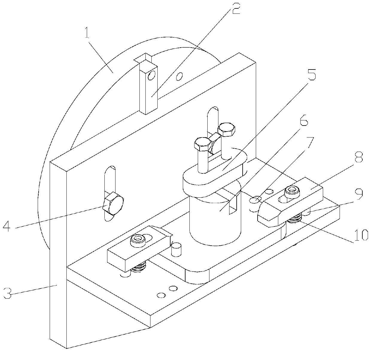
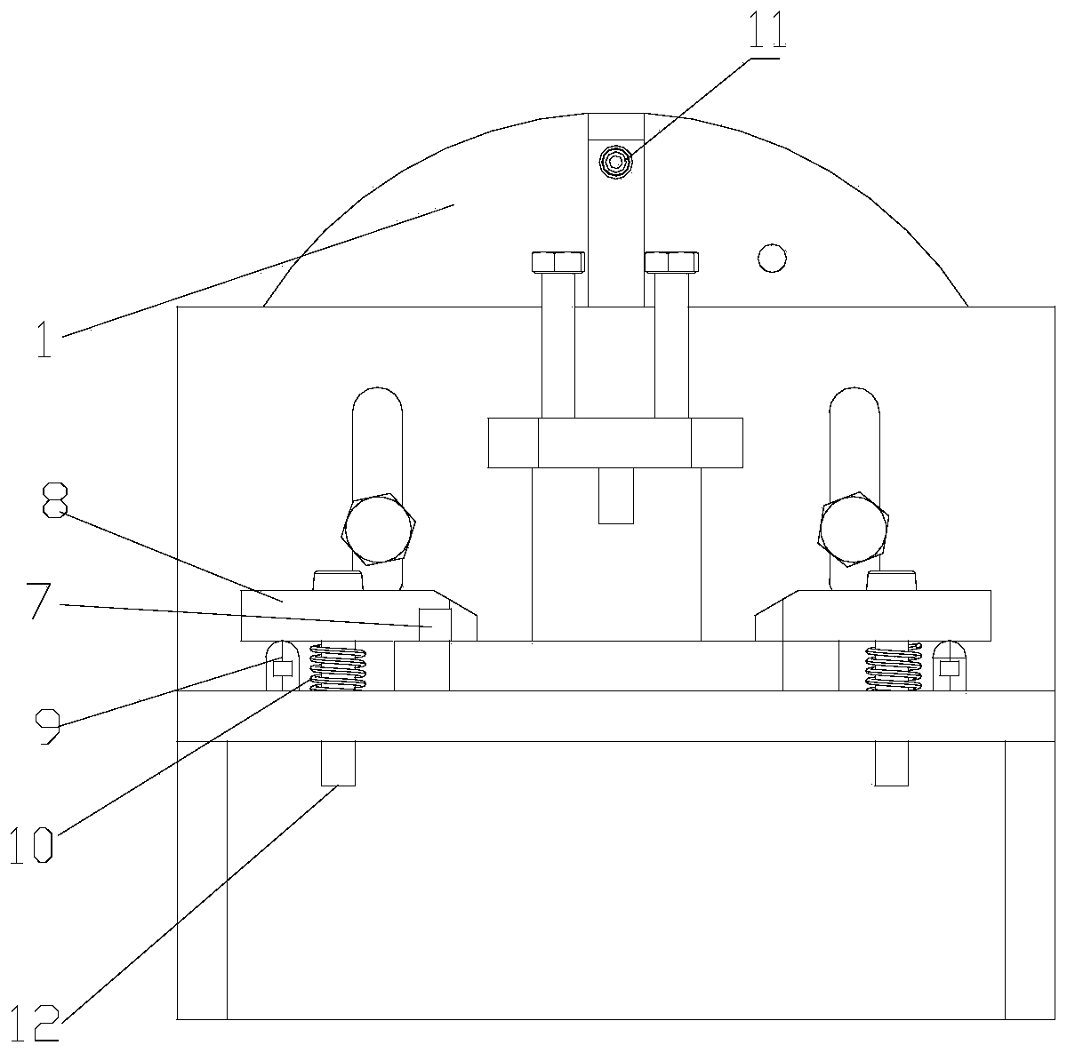
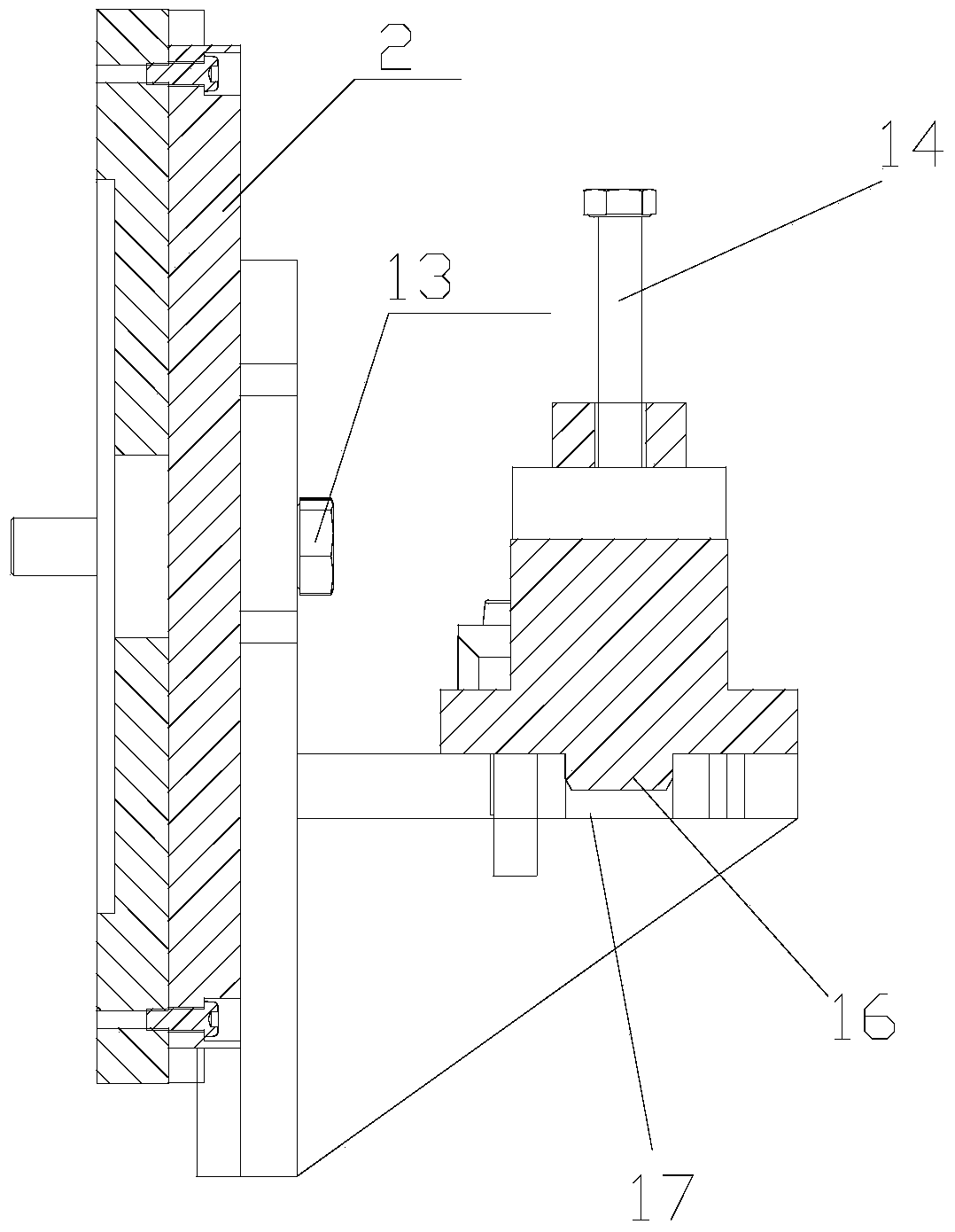
[0016] Such as Figure 1-5 As shown, a valve body shaft hole processing tire of the present invention includes a T-shaped positioning plate 3 assembled with a lathe faceplate 1 through a guide rail 2, and a T-shaped structure is installed on the flat part of the T-shaped positioning plate. The rotating body 6, the rotating body has a cylindrical portion that is matched with the valve body to be processed and a bottom plate connected with the cylindrical portion, the bottom of the bottom plate forms a circular hole 17 on the flat surface that can be rotatably fitted together Bottom boss 16, described plane part is provided with rotating body pressure plate 8, to press described rotati...


PUM


Abstract

The invention discloses a valve body shaft hole machining mould which comprises a T-shaped positioning plate assembled with a lathe faceplate through a guide rail, a rotating body of a T-shaped structure is installed on the plane portion of the T-shaped positioning plate, and the rotating body is provided with a cylindrical portion matched with a valve body to be machined and a bottom plate connected with the cylindrical portion. A lower protruding column assembled together with an upper round hole of the plane part in a rotating fit mode is formed at the bottom of the bottom plate, a rotatingbody pressing plate is arranged on the plane part so as to press the rotating body on the plane part to be fixed, and a valve body fixing plate is installed at the upper end of the rotating body through a bolt in a connected mode. The positions of the bottom plate and the plane part of the rotating body are positioned through positioning pins. According to the valve body shaft hole machining clamping mould, through the technical scheme, a corresponding valve body can be conveniently positioned, so that shaft holes in the two sides of the valve body are conveniently machined, the structure issimple, and use is convenient.

Description

technical field [0001] The invention relates to the technical field of mold processing, in particular to a mold for machining a shaft hole of a valve body. Background technique [0002] Due to the butterfly valve (see Figure 5 As shown), the valve body has a special structure, which has a cylindrical part, and on both sides of the cylindrical part, there is a radial pipe body connected through the cylindrical part. Therefore, there are difficulties in processing and positioning, especially in processing The problem of inconvenient positioning exists in the shaft holes of the two radial pipe body parts. Contents of the invention [0003] The object of the present invention is to provide a mold for machining the shaft hole of the valve body aiming at the technical defects in the prior art. [0004] The technical scheme adopted for realizing the purpose of the present invention is: [0005] A valve body shaft hole processing tire, including a T-shaped positioning plate ass...

Claims


Application Information

Patent Timeline
Patent Type & Authority Applications(China)
IPC IPC(8): B23Q3/12B23Q7/00
CPCB23Q3/12B23Q7/00B23Q2703/10
Inventor 程川张亚平郭宝霞孙亚楠张富君贾雪晴
Owner TIANJIN GALAXY VALVE
Learn More