Turnover box conveying device

A technology of transmission device and turnover box, applied in conveyor control device, transportation and packaging, conveyor and other directions, can solve problems such as affecting the quick response ability of small order quantity, increasing the difficulty of production managers, and blocking the line of sight of managers.

Pending Publication Date: 2020-03-24
苏州优王电子科技有限公司
View PDF16 Cites 2 Cited by
  • Summary
  • Abstract
  • Description
  • Claims
  • Application Information

AI Technical Summary

Problems solved by technology

[0007] However, still taking clothing as an example, as the pace of clothing style changes is getting faster and faster, and the order volume of each style is getting smaller and smaller, a production line has to change several styles almost every day, and even special customization of one product occurs. , if the rhythmic single-piece flow method is still adopted, it will undoubtedly add great difficulty to the production manager if the style changes and the production balance needs to be re-arranged and the time spent by different stations, and it will even be impossible to adopt the rhythmic One-piece flow management, because beat-type one-piece flow management is more suitable for products with a slightly larger batch size and a certain production cycle time.
[0008] The intelligent hanging system also has a certain application status in the production process of the aforementioned light industrial products, and can also automatically transmit according to the production path programmed by the computer, but there are the following disadvantages: First, because the products such as clothing are hung in the air, As a result, it blocks the line of sight of the managers and creates management blind spots, which cannot reflect effective management; secondly, due to the accumulation of inventory, it will lengthen the production cycle to a certain extent and affect the ability to respond quickly to small orders; thirdly, due to the visualization of the entire assembly line The effect is poor, so whether the employees' working conditions are good or not, the production efficiency is fast or slow, whether abnormal problems in production can be found in time, etc., cannot meet the expectations of the industry; Fourth, there is no certain urgent pressure on employees. It causes employees to slack off at work and affects efficiency; fifth, there is no effective measure for managers to deal with abnormalities or bottlenecks in a timely manner, and the executive power of managers cannot be reflected; sixth, due to the limitation of hanging clothes hangers, only transport Fewer cutting pieces, that is, only simple garments, or partial assembly processes of complex styles, have limited improvement in production efficiency and limited help to the entire production line
[0009] In view of the fact that the aforementioned Toyota beat-type single-piece flow system and intelligent hanging system are difficult or even impossible to make adaptive changes to the production process of products such as clothing with frequent style changes and small batch orders, it is necessary to explore flexible The technical solution to be introduced below is produced under this background

Method used


Image

  • Turnover box conveying device
  • Turnover box conveying device
  • Turnover box conveying device

Examples


Embodiment Construction

[0027] In order to understand the technical essence and beneficial effects of the present invention more clearly, the applicant will describe in detail the following examples, but the descriptions of the examples are not intended to limit the solutions of the present invention. Equivalent transformations that are only formal but not substantive should be regarded as the scope of the technical solution of the present invention.

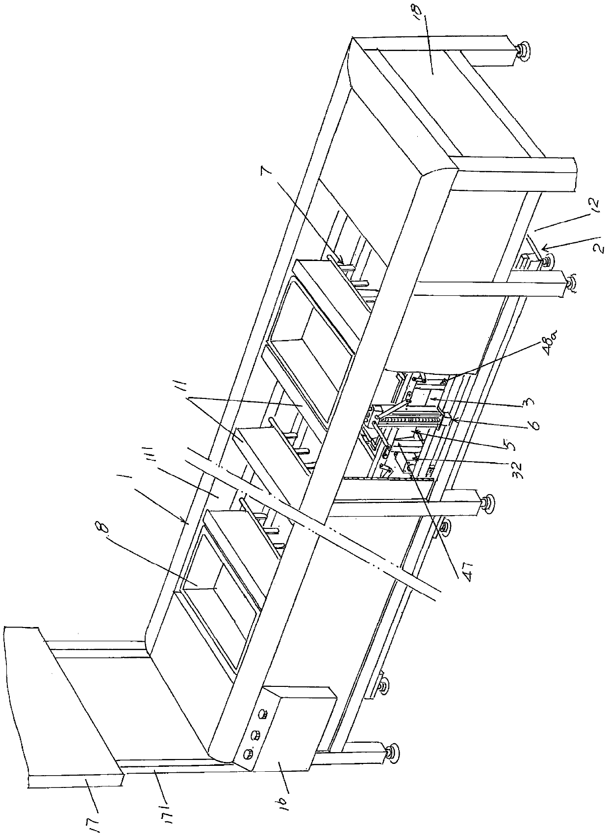
[0028] In the following descriptions, all concepts related to directionality or orientation of up, down, left, right, front and back are based on figure 1 The shown position status is a reference, so it cannot be understood as a special limitation on the technical solution provided by the present invention.

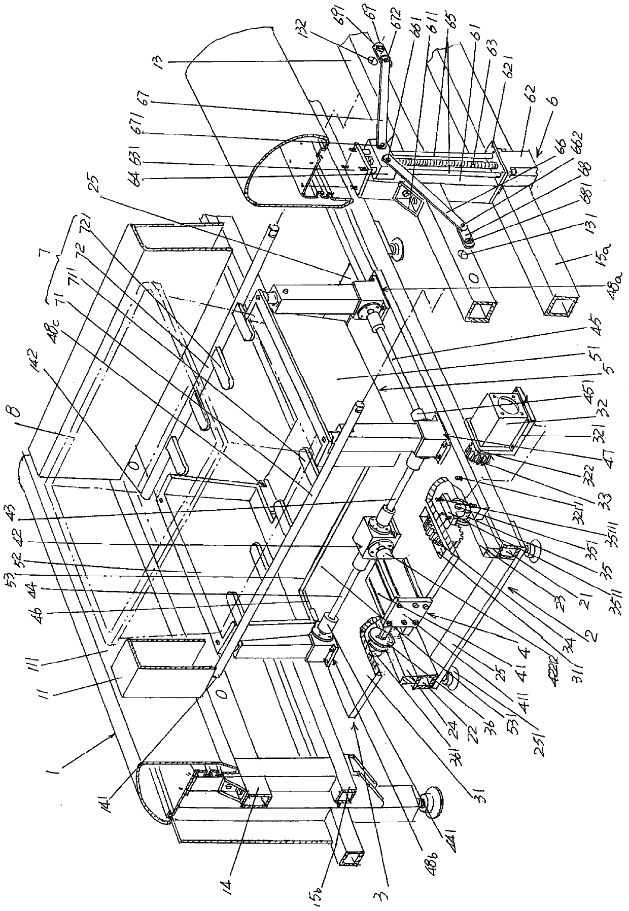
[0029] See figure 1 and figure 2 , shows a first-class water tank 1, the water tank 1 is supported on the floor of the place of use in the use state, and the upper part of the water tank 1 and along the length direction of the water tank 1 are ...


PUM


Abstract

The invention relates to a turnover box conveying device and belongs to the technical field of light industrial product assembly line production equipment. The device comprises a gutter channel, a movable trolley frame, a movable trolley, a turnover box supporting box lifting mechanism, a turnover box supporting box, a turnover shaft driving mechanism and a turnover box supporting and releasing mechanism, wherein turnover box cavity partition plates are fixed to an upper portion of the gutter channel in the length direction of the gutter channel, the space between every two adjacent turnover box cavity partition plates forms a turnover box cavity, a gutter channel trolley receding cavity is formed between a lower portion of the gutter channel and a terrace, the movable trolley frame is arranged in the gutter channel trolley receding cavity, the moving trolley is arranged on the moving trolley frame, the turnover box supporting box lifting mechanism is arranged on the moving trolley, the turnover box supporting box is connected with the turnover box supporting box lifting mechanism, the turnover shaft driving mechanism is arranged on the front side or the rear side of the gutter channel, and the turnover box supporting and releasing mechanism is arranged between the front side and the rear side of the water flowing groove and connected with the turnover shaft driving mechanism.The device is advantaged in that the requirement that the turnover box rises or falls at the position, corresponding to any workstation on one side of the assembly line groove, of the turnover box according to needs and is transferred to the lower workstation is met, and adaptability to flexible changes of small-batch orders and even special customization is embodied.

Description

technical field [0001] The invention belongs to the technical field of assembly line production equipment for light industrial products, and in particular relates to a turnover box transmission device. Background technique [0002] The turnover box mentioned above can also be called a "turnaround box" or a turnover tray. The light industrial products mentioned above mainly refer to clothing, but are not limited to clothing. For example, it can be shoes, hats, bags, etc., as well as electrical and electronic products, dolls and toys, etc. [0003] Taking a large-scale garment factory as an example, the production process of a piece of clothing includes cutting, sewing, opening buttonholes, buttoning (referred to as buttoning), bagging, collaring, sleeves, placket and There are several processes such as ironing, which are often carried out in a division of labor and automation. [0004] The cyclic transmission device and the matching intelligent control dispatching system ha...

Claims


Application Information

Patent Timeline
Patent Type & Authority Applications(China)
IPC IPC(8): B65G35/00B65G37/00B65G43/00
CPCB65G35/00B65G37/00B65G43/00
Inventor 尹术超
Owner 苏州优王电子科技有限公司
Why Eureka
Try Eureka