

Tunnel arch frame structure and process for reinforcing soft soil layer by driving locking feet in advance
A technology of weak soil layer and frame structure, applied in tunnels, tunnel linings, mining equipment, etc., can solve problems such as adverse social impact, large traffic flow, pipeline burst, etc., to improve anti-settling ability, small pipe diameter, reduce side the effect of pressure
- Summary
- Abstract
- Description
- Claims
- Application Information
AI Technical Summary
Problems solved by technology
Method used
Image

Examples
Embodiment Construction
[0031] Specific embodiments of the present invention are provided below, and it should be noted that the present invention is not limited to the following specific embodiments, and all equivalent transformations done on the basis of the technical solutions of the present application all fall within the scope of protection of the present invention.
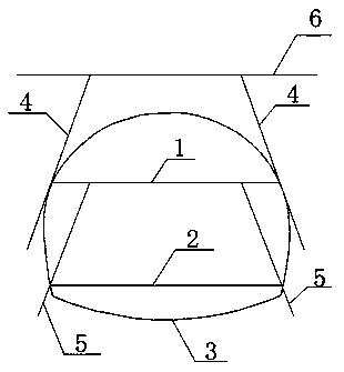
[0032] A tunnel arch structure with locking feet in advance to reinforce the weak soil layer. The locking foot conduit at the arch foot position of the steel arch frame on the upper step 1 is the ground advanced locking foot conduit 4, and the ground advanced locking foot conduit 4 is advanced from the ground 6. The foot-locking conduit installed, the ground-leading foot-locking conduit 4 is connected to the steel arch of the upper step 1; Leading foot-locking conduit 5 is a foot-locking conduit laid in advance from upper step 1, and leading-locking foot conduit 5 of middle and lower steps is connected with steel arch frame of middl...
PUM
| Property | Measurement | Unit |
|---|---|---|
| Diameter | aaaaa | aaaaa |
Abstract
Description
Claims
Application Information