A test system for micro-flow and small-load water pumps

A test system and small load technology, which is applied in the field of water pump test system and small flow and small load water pump test system, to realize the automatic control of the system, meet the requirements of long-term test, and eliminate the effect of pressure pulsation

Active Publication Date: 2022-04-19
XIAN AERO ENGINE CONTROLS
View PDF9 Cites 0 Cited by
  • Summary
  • Abstract
  • Description
  • Claims
  • Application Information

AI Technical Summary

Problems solved by technology

[0003] In order to achieve the purpose of the present invention: in order to solve the problems that occur during the use of the existing tester and optimize the system structure, only a new design that can accurately specify the test load and accurately test the output technical indicators can also meet its long-term test requirements. Tester for test requirements
It is used to meet the test requirements of specimens, meet the urgent needs of national defense, and solve the defects in the use of existing testers, and can also fill a gap in the country

Method used


Image

  • A test system for micro-flow and small-load water pumps

Examples


Embodiment 1

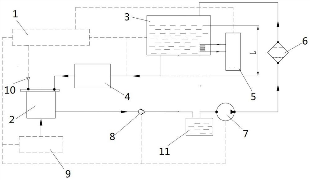
[0018] Such as figure 1 As shown, a test system for a micro-flow and small-load water pump includes a measurement and control system 1, a metering container 2, a water tank 3, a test pump 4, a flow measurement device 9 and a pressure source 10;

[0019] The water tank is communicated with the inlet of the test pump, and the outlet of the test pump is communicated with the metering container, and the metering container is also communicated with the pressure source, and the pressure source is used to simulate the outlet pressure environment of the test pump, and the metering container is equipped with a flow test device. For measuring the outlet flow rate of the test pump, the measured water is discharged from the outlet of the metering container; the liquid level of the water tank is higher than the level of the test pump, so that the liquid level of the water tank forms a drop L with the test pump; The test system receives the flow data measured by the control flow measuring d...

Embodiment 2

[0027] Such as figure 1 As shown, a test system for a micro-flow and small-load water pump includes a measurement and control system 1, a metering container 2, a water tank 3, a test pump 4, a flow measurement device 9 and a pressure source 10;

[0028] The water tank is communicated with the inlet of the test pump, and the outlet of the test pump is communicated with the metering container, and the metering container is also communicated with the pressure source, and the pressure source is used to simulate the outlet pressure environment of the test pump, and the metering container is equipped with a flow test device. For measuring the outlet flow rate of the test pump, the measured water is discharged from the outlet of the metering container; the liquid level of the water tank is higher than the level of the test pump, so that the liquid level of the water tank forms a drop L with the test pump; The test system receives the flow data measured by the control flow measuring d...


PUM


Abstract

The invention relates to a test system for a micro-flow and small-load water pump, comprising a measurement and control system, a metering container, a water tank, a test pump, flow measurement equipment and a pressure source; the liquid level of the water tank is higher than the level of the test pump, A drop L is formed between the liquid level of the water tank and the test pump; the test system receives the flow data measured by the control flow measuring device, and controls the pressure of the pressure source. The invention adopts the method of controlling the liquid level of the water tank to set the inlet pressure and stabilize the inlet pressure; and adopts the method of gas counterpressure in the metering container to simulate the outlet load, eliminating the pressure pulsation at the outlet of the pump; adopts the real-time measurement method of the outlet flow test device to meet the small Flow online test requirements; the test system adopts automatic control and recording to realize automatic control of the system and meet the needs of long-term tests.

Description

technical field [0001] The invention relates to the technical field of pump testing, in particular to a testing system for a water pump, in particular to a testing system for a water pump with a small flow rate and a small load. Background technique [0002] At present, the micro-flow and small-load water pump is one of the key components in the water system of the space station, and its flow and load pressure are extremely small (inlet pressure: 0~0.01MPa, flow rate: 2±0.3ml / time, inlet and outlet pressure difference: 0~0.05± 0.02MPa, water temperature: 5±2°C, 40±2°C), if the test method of industrial system products is used, the test is more difficult. The existing tester is a closed circulation system. The inlet of the system is a low-pressure pump to depressurize and supply liquid, and the outlet is realized by pipeline interception. The flow test is a closed-loop measurement. The following defects appear: 1. The inlet pressure fluctuates greatly; 2. The outlet pipeline...

Claims


Application Information

Patent Timeline
Patent Type & Authority Patents(China)
IPC IPC(8): F04B51/00
CPCF04B51/00
Inventor 李鹏飞王均儒晁文雄夏志海田浩玲
Owner XIAN AERO ENGINE CONTROLS
Why Eureka
Try Eureka