Device for tension test of strain clamp wire assembly

A technology of tension clamps and assemblies, which is applied in the direction of measuring devices, applying stable tension/pressure to test material strength, instruments, etc., can solve the problem that the tension clamp wire assembly is easy to detach, easy to rotate by mistake, and affect the test Results and other issues, to achieve the effect of reducing shaking, ensuring the quality of fixing, and improving installation efficiency

Inactive Publication Date: 2020-03-24
ZHEJIANG HUADIAN EQUIP TESTING INST +2
View PDF5 Cites 0 Cited by
  • Summary
  • Abstract
  • Description
  • Claims
  • Application Information

AI Technical Summary

Problems solved by technology

[0002] The wire assembly of the strain-resistant clamp is realized by twisting the single wire around the stranded wire shaft at an equal angular velocity and moving the stranded wire forward at a uniform speed. After the tension clamp wire assembly is produced, it is necessary to carry out a tension test on the tension clamp wire assembly. The existing tension clamp wire assembly has passed the tensile machine test during the test, while the existing tension clamp wire assembly has passed the tensile test. The pay-off reel for the wire clamp wire assembly is easy to rotate by mistake during the test, and the tension wire clamp wire assembly is easy to detach during the wire assembly process of the tension wire clamp wire assembly, which affects the test results

Method used


Image

  • Device for tension test of strain clamp wire assembly
  • Device for tension test of strain clamp wire assembly

Examples


Embodiment Construction

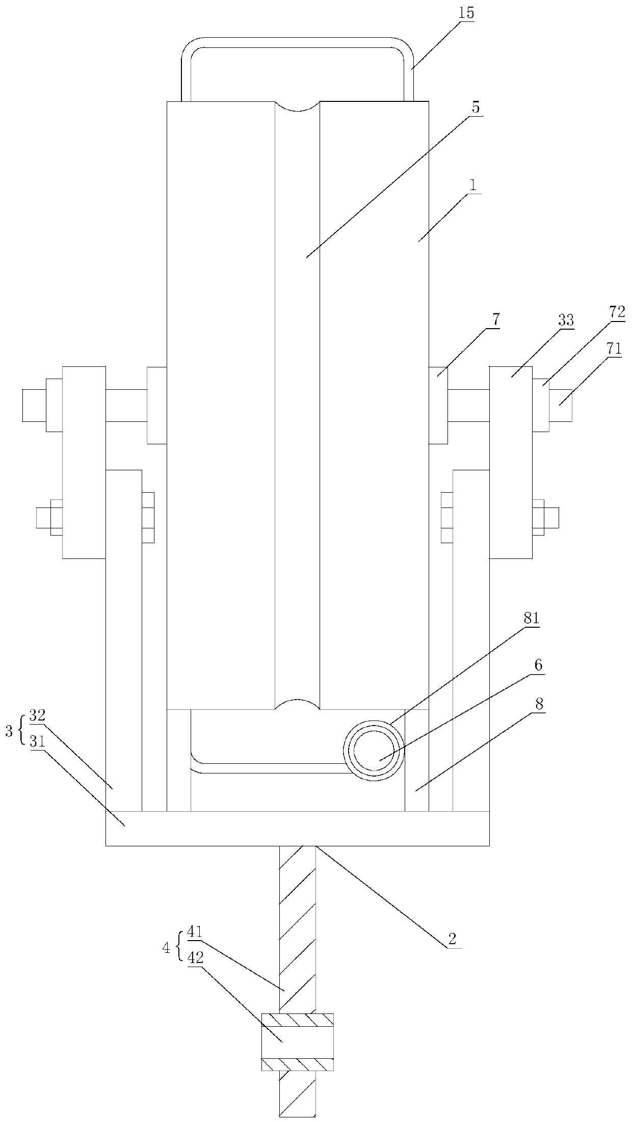
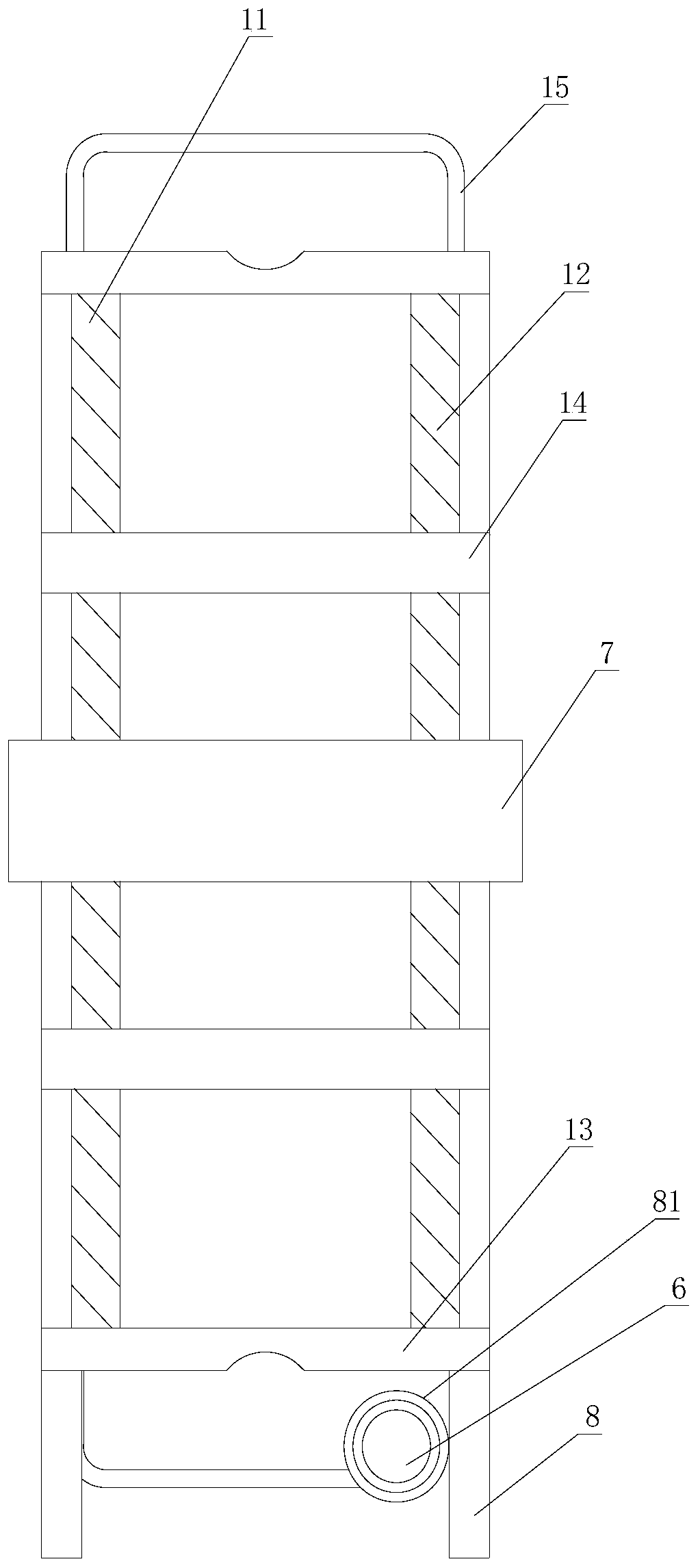
[0017] Such as figure 1 , figure 2 As shown, a device for the tension test of the tension clamp wire assembly includes a spoke 1 and a connecting piece 2, and the connecting piece 2 includes a first connecting part 3 connected to the spoke 1, and a section connected to the tensile force The second connecting part 4 connected to the fixed end of the testing machine, the second connecting part 4 is arranged on the first connecting part 3, and the spoke 1 also includes a rotating shaft 7, and the first connecting part 3 is arranged on the rotating shaft 7 Connected screw rod 71, the screw rod 71 is locked on the first connecting part 3 through the lock nut 72 after passing through the first connecting part 3, and the outer circumferential side wall of the spoke 1 is provided with an annular recess for fixing the sample. Groove 5, and the guide sleeve 6 that is convenient for the sample to pass through, and the sample is connected to the loading end of the tensile testing machin...


PUM


Abstract

The invention relates to a device for a tension test of a strain clamp wire assembly. The device comprises a spoke and a connecting piece, the connecting piece comprises a first connecting part and asecond connecting part, the spoke further comprises a rotating shaft, a screw rod connected with the first connecting part is arranged on the rotating shaft, an annular groove and a guide sleeve are arranged on the side wall of the outer circumference of the spoke, and a sample penetrates through the guide sleeve and then is connected with the loading end of a tension tester. The device has the advantages that a sample to be tested is fixed on the outer circumferential side wall of the spoke through the annular groove; one end of the sample penetrates through the guide sleeve and then is connected with a loading end of a tension tester; finally, the spoke is fixedly connected to the fixed end of the tensile testing machine through the connecting piece, and due to the fact that the spoke isrotationally connected with the first connecting part in the connecting process, the sample can be rapidly and stably wound on the annular groove of the spoke, the tensioning test of the sample in the bending process is achieved, misoperation of the spoke is prevented, and the test quality is improved.

Description

technical field [0001] The invention relates to a device for the tension test of a tension clamp wire assembly. Background technique [0002] The wire assembly of the strain-resistant clamp is realized by twisting the single wire around the stranded wire shaft at an equal angular velocity and moving the stranded wire forward at a uniform speed. After the tension clamp wire assembly is produced, it is necessary to carry out a tension test on the tension clamp wire assembly. The existing tension clamp wire assembly has passed the tensile machine test during the test, while the existing tension clamp wire assembly has passed the tensile test. The pay-off reel of the wire clamp wire assembly is easy to rotate by mistake during the test, and the tension wire clamp wire assembly is easy to detach during the unwinding process of the tension wire clamp wire assembly, thus affecting the test results. Contents of the invention [0003] The technical problem to be solved by the pres...

Claims


Application Information

Patent Timeline
Patent Type & Authority Applications(China)
IPC IPC(8): G01N3/08G01N3/04G01N3/02
CPCG01N3/08G01N3/04G01N3/02
Inventor 马恒吕中宾郑文悦叶中飞陈玲伍川高义波庞锴杨丽莉
Owner ZHEJIANG HUADIAN EQUIP TESTING INST
Why Eureka
Try Eureka