High-voltage switch cabinet structure

A high-voltage switchgear and cabinet technology, applied in the field of switchgear, can solve the problems of small space in the bus room B, occupying space, affecting the conductive performance of the busbar copper bars, etc., to achieve the effect of large remaining space and easy disassembly

Pending Publication Date: 2020-03-24
SOUTH CHINA ELECTRIC DEV XIAMEN
View PDF0 Cites 0 Cited by
  • Summary
  • Abstract
  • Description
  • Claims
  • Application Information

AI Technical Summary

Problems solved by technology

[0003] 1. The current transformer 1' and the grounding switch 2' in the cable room A of the switch cabinet are installed at the back of the cabinet, occupying most of the space at the back of the cabinet; the installation positions of the current transformer and the grounding switch increase The installation of components is difficult, and it is not conducive to on-site operation and later maintenance of cu

Method used


Image

  • High-voltage switch cabinet structure
  • High-voltage switch cabinet structure
  • High-voltage switch cabinet structure

Examples


Embodiment Construction

[0038] In order to further explain the technical solution of the present invention, the present invention will be described in detail below through specific examples.

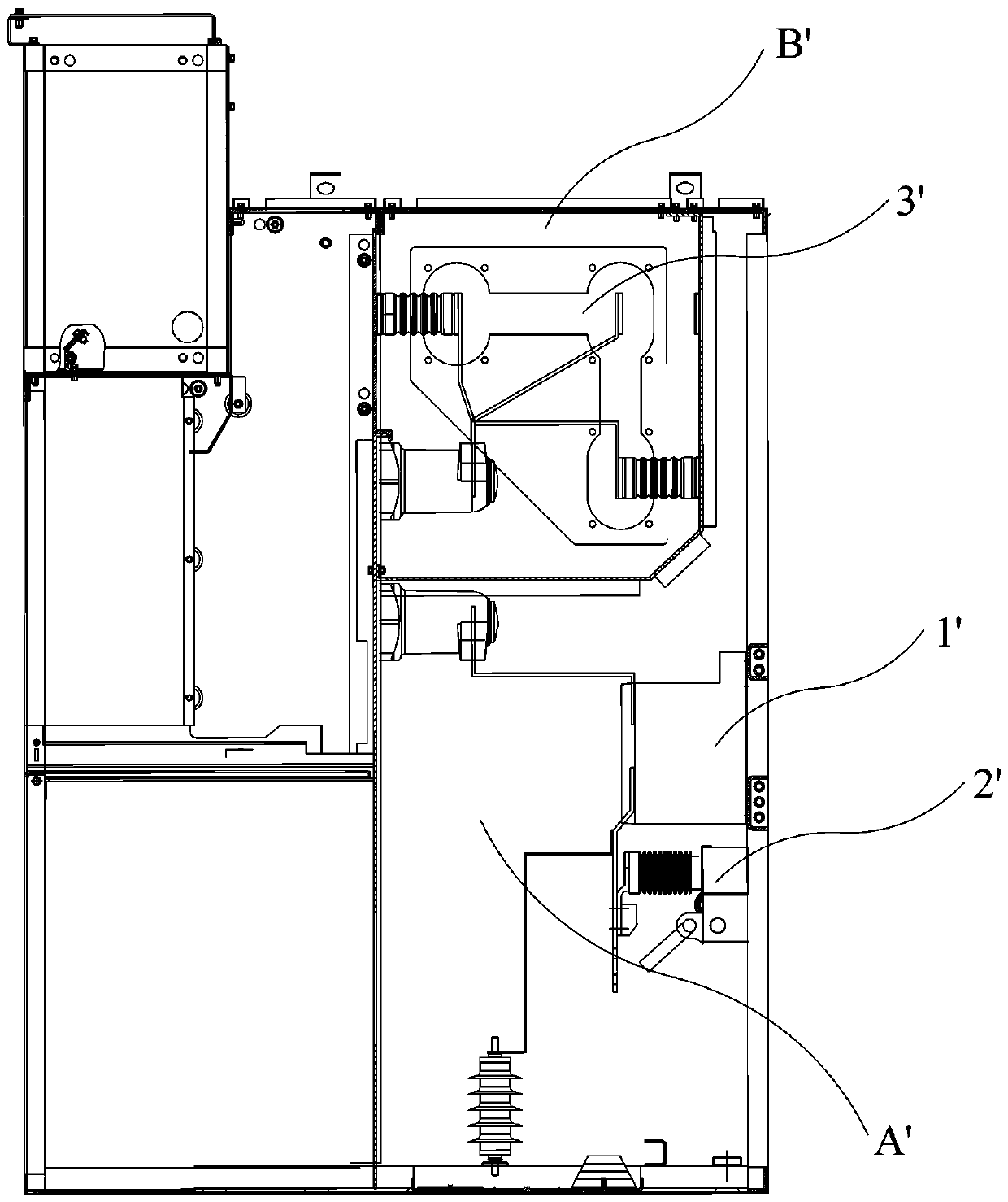
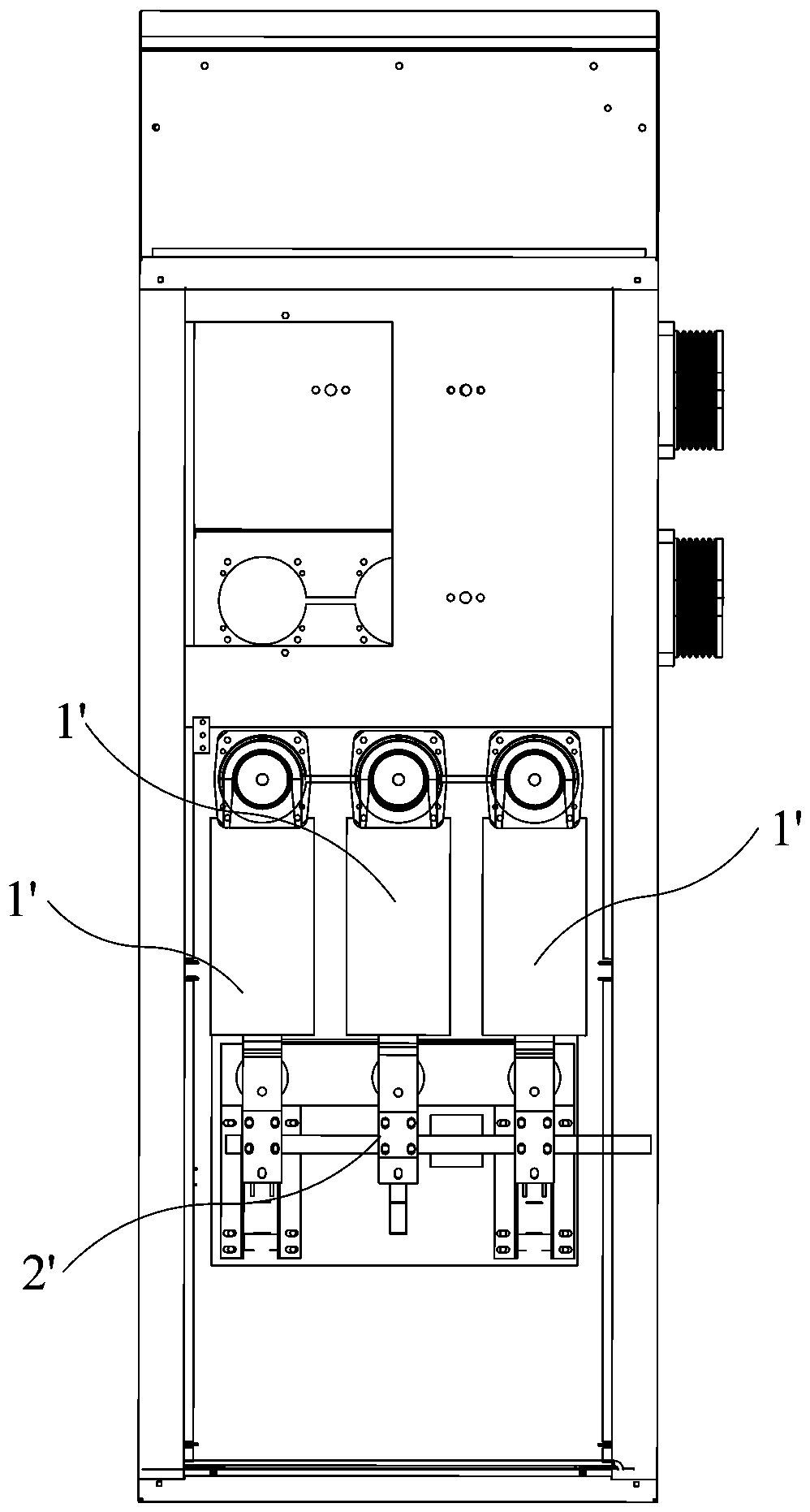
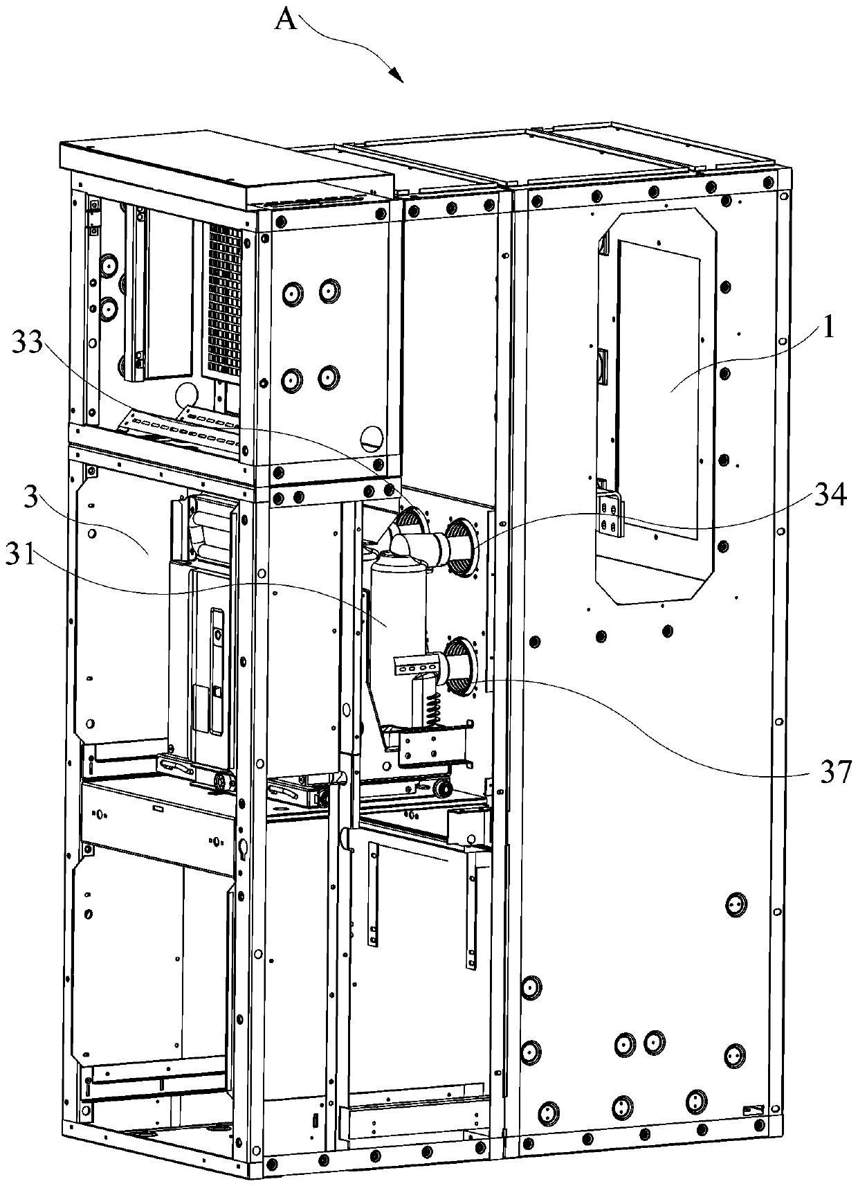
[0039] Such as Figure 3 to Figure 11 As shown, the present invention discloses a high-voltage switchgear structure, which includes a cabinet A, and the cabinet A is provided with a busbar room 1, a cable room 2 and a circuit breaker room 3, wherein the circuit breaker room 3 is located at the front of the cabinet A , the busbar room 1 and the cable room 2 are located at the rear of the cabinet A and the cable room 2 is below the busbar room 1, the circuit breaker room 3 is separated from the busbar room 1 and the cable room 2 by a safety partition 4, and the busbar room 1 is separated by a bend The plate 5 is separated from the cable chamber 2. The bent plate 5 is in an L-shaped structure. The bent plate 5 includes a connected horizontal plate 51 and a vertical plate 52. The horizontal plate 51 and the vertica...


PUM


Abstract

The invention discloses a high-voltage switch cabinet structure. The power distribution cabinet comprises a cabinet body, a bus chamber, a cable chamber and a circuit breaker chamber are arranged in the cabinet body. The circuit breaker chamber is separated from the bus chamber and the cable chamber through a safety separator plate. The bus chamber is separated from the cable chamber through a bent plate, a three-phase circuit breaker is installed in the circuit breaker chamber, a busbar is installed in the bus chamber, a current transformer, a lightning arrester and a grounding switch are installed in the cable chamber, the current transformer is inversely installed below the bent plate, and the lightning arrester and the grounding switch are installed on the safety partition plate. According to the high-voltage switch cabinet structure, the current transformer and the grounding switch can be conveniently overhauled.

Description

technical field [0001] The invention relates to the field of switch cabinets, in particular to a high-voltage switch cabinet structure. Background technique [0002] Cooperate figure 1 and figure 2 As shown, the following problems exist in the existing high-voltage switchgear: [0003] 1. The current transformer 1' and the grounding switch 2' in the cable room A of the switch cabinet are installed at the back of the cabinet, occupying most of the space at the back of the cabinet; the installation positions of the current transformer and the grounding switch increase The installation of components is difficult, and it is not conducive to on-site operation and later maintenance of current transformers and grounding switches; [0004] 2. The cabinet body of the switchgear adopts a stepped structure, and the bus bar 3' of the bus bar room B on the top of the cabinet body adopts an L-shaped arrangement, resulting in a narrow space in the bus bar room B, which is not conducive...

Claims


Application Information

Patent Timeline
IPC IPC(8): H02B1/32H02B1/36H02B1/20H02B1/21H02B1/04H02B1/16
CPCH02B1/04H02B1/16H02B1/20H02B1/202H02B1/21H02B1/32H02B1/36
Inventor 杨玉福陈腾林简兆辉林艺娜林志强林晓裕王辉罗志婷
Owner SOUTH CHINA ELECTRIC DEV XIAMEN
Why Eureka
Try Eureka