
A lifting rod structure for power substation assembly

A technology for substations and lifting rods, which is applied to electrical components, switchgear, transportation and packaging, etc. It can solve the problems of damaged insulation sheath, poor stable positioning of cables, etc., and achieve the effect of avoiding falling off

Active Publication Date: 2021-06-22
国能荥阳热电有限公司
View PDF9 Cites 0 Cited by
  • Summary
  • Abstract
  • Description
  • Claims
  • Application Information

AI Technical Summary

Problems solved by technology

[0004] In order to solve the above technical problems, the present invention provides a lifting rod structure for power substation assembly, to solve the problem that most lifting rods use hooks and steel wire ropes to directly hang cables, causing the outer skin of the cable and the insulating skin of the inner conductive wire to be easily squeezed The problem of damage and damage, and the poor effect on the stable positioning of the cable

Method used


Image

  • A lifting rod structure for power substation assembly
  • A lifting rod structure for power substation assembly
  • A lifting rod structure for power substation assembly

Examples


Embodiment

[0030] as attached figure 1 to attach Figure 8 Shown:

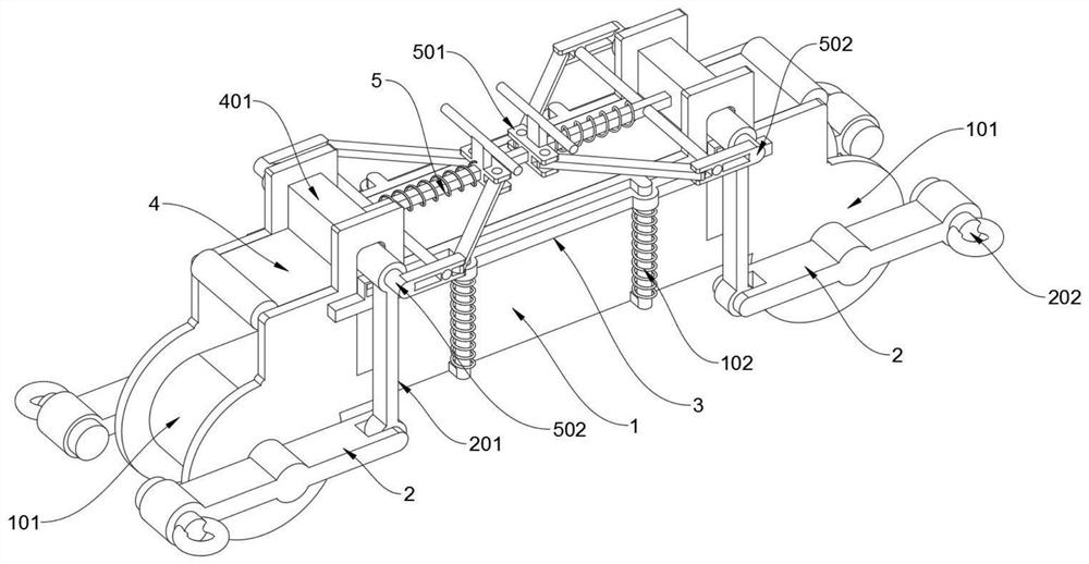
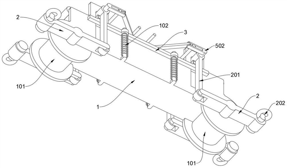
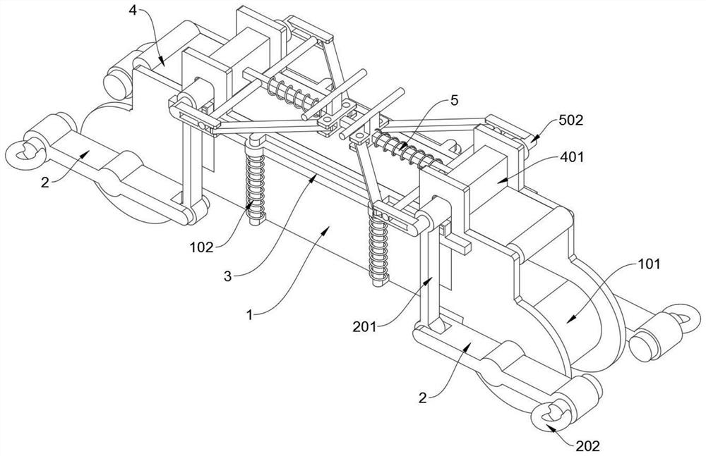
[0031] The present invention provides a lifting rod structure for power substation assembly, which includes a square boom 1 and a pressure plate 4. A wire release trough is opened on the top of the square boom 1 in a left and right direction. The two sides of the wire discharge trough Two chutes are symmetrically opened on the wall, and the tops of the four chutes all extend upwards to support a track frame; In the wire slot of the square suspender 1.

[0032] Wherein, the square suspender 1 includes a guide roller 101 and a positioning rod 102; two guide rollers 101 are symmetrically supported at the left and right ends of the square suspender 1, and a circle of winding grooves is provided on the two guide rollers 101, The two winding slots are connected to the wire slots on the square suspender 1, and the cables are bent and drooped on the two guide rollers 101. The circumferential ring surfaces of the two guide rol...


PUM


Abstract

The present invention provides a lifting rod structure for power substation assembly, which includes a square suspension rod and a pressure plate. A wire-releasing trough is opened on the upper side of the square suspension rod. The side walls on both sides of the wire-releasing groove There are two chutes symmetrically penetrated, and the tops of the four chutes all extend upwards to support a track frame; the pressure plate is set up in a rectangular shape with a smooth transition at the left and right ends, and its lower part is installed on the square suspender. In the cable trough, when the four suspension rings receive the upward pull force from the wire rope, the four swing plates can pull down the four connecting rods, so that it drives the pressure plate to slide downward, and the cable is squeezed and fixed on the square suspension with a stable top pressure. In the wire trough on the pole, avoid the cable slipping and falling off the square suspender during the hoisting process, and the circumferential ring surfaces of the two guide rollers can play the role of arc excessively dispersing stress, avoiding excessive drooping stress Concentration causes the cable sheath and internal conductive wires to be squeezed and injured.

Description

technical field [0001] The invention belongs to the technical field of lifting rods, and more specifically relates to a lifting rod structure used for assembling a power substation. Background technique [0002] During the assembly operation of power substations, a large number of large conductive cables with large cross-sectional areas need to be lifted to a high place for wiring or to be connected to transformers. Usually, the cables will be hoisted and installed with a crane. To cooperate with the hoisting of the crane, it is necessary to design a A special cable lifting rod structure, for example, the patent No. CN201721062836.X discloses that the ground wire lifting rod includes a rod body, a load-bearing hook, a buzzer electroscope and a fixed pulley, wherein the rod body is an insulator and one end is fixedly connected to a The load-bearing hook, the other end of the rod body is provided with the fixed pulley, the buzzer electroscope is arranged on the load-bearing ho...

Claims


Application Information

Patent Timeline
Patent Type & Authority Patents(China)
IPC IPC(8): H02G1/04
CPCB66C1/10H02B3/00H02G3/34
Inventor 沈梦然沈文齐
Owner 国能荥阳热电有限公司
Learn More