
Quality analysis device and quality analysis method

A quality analysis and quality technology, applied in the direction of comprehensive factory control, program control, electrical program control, etc., can solve problems such as ambiguity, and achieve the effect of easy bad conditions

Active Publication Date: 2020-03-24
MITSUBISHI ELECTRIC CORP
View PDF7 Cites 0 Cited by
  • Summary
  • Abstract
  • Description
  • Claims
  • Application Information

AI Technical Summary

Problems solved by technology

There is a problem that, when a defect factor candidate is extracted based on knowledge and experience of a manufacturing site, it is not clear whether the defect factor candidate is a real defect factor

Method used


Image

  • Quality analysis device and quality analysis method
  • Quality analysis device and quality analysis method
  • Quality analysis device and quality analysis method

Examples


Embodiment approach 1

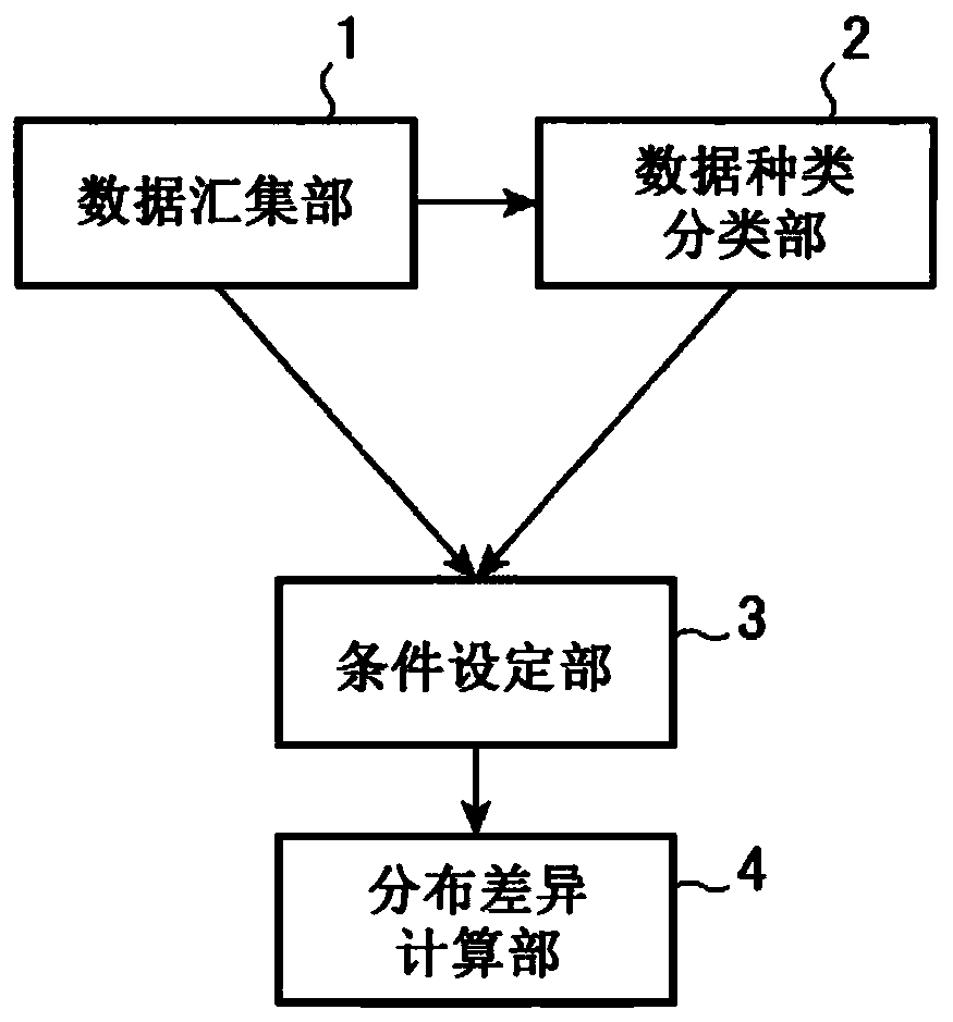
[0029] figure 1 It is a configuration diagram of the quality analyzer according to the present embodiment.

[0030] The quality analysis device according to this embodiment includes a data collection unit 1 , a data type classification unit 2 , a condition setting unit 3 , and a distribution difference calculation unit 4 . The data collection unit 1 is a processing unit that acquires quality data and device information data. The data type classification unit 2 is a processing unit that classifies the quality data and device information data acquired by the data collection unit 1 according to a set predetermined rule. The condition setting unit 3 is for the data acquired by the data collection unit 1 or the data classified by the data type classification unit 2, for the data items to be aggregated, the reference conditions representing the basic conditions for quality analysis, and the standard conditions representing the quality analysis. A processing unit that sets comparis...

Embodiment approach 2

[0079] In Embodiment 2, event data is also included as the data obtained by the data collection unit 1, and the relationship between the value of the data item obtained in Embodiment 1 and the event data is obtained, wherein the event data represents , about the device, what kind of event happened.

[0080] That is, the data item with a high degree of deviation between the reference condition and the comparison condition extracted by the distribution difference calculation unit 4 is only a phenomenon that is statistically obtained from the quality data and the device information data and has a high possibility of failure ( Hereinafter, these are referred to as factor candidates). Therefore, in the second embodiment, the event data confirmed by experts in the past is correlated with the value obtained by collecting the change of OK / NG of the factor candidate and the statistic. Accordingly, it is possible to obtain a result equivalent to a result reflecting an expert's opinion....


PUM


Abstract

According to the present invention, a data aggregation unit (1) acquires quality data and device information data. A condition setting unit (3) sets a data item to be summed up, a criterion conditionthat indicates a condition to be a basis of a quality analysis target, and a comparison condition that indicates a condition to be a target of quality analysis with respect to the quality data and thedevice information data acquired by the data aggregation unit (1). A distribution difference calculation unit (4) extracts, from the quality data and the device information data acquired by the dataaggregation unit (1), data satisfying the criterion condition of the data item set by the condition setting unit (3) and data satisfying the comparison condition, and calculates a frequency distribution for each data item, and outputs data for indicating a deviation degree in frequency distribution between the criterion condition and the comparison condition.

Description

technical field [0001] The present invention relates to a quality analysis device and a quality analysis method capable of estimating causes of trend changes in product manufacturing processes and test processes, and causes of product failures. Background technique [0002] The causes of defects at the manufacturing site (fluctuation in quality, deterioration in yield, deterioration in tact time, increase in defective products, device failure, etc.) are often clarified from the knowledge and experience of the manufacturing site. There is a problem that, when a defect factor candidate is extracted based on knowledge and experience of a manufacturing site, it is not clear whether the defect factor candidate is a true defect factor. [0003] When extracting the cause of a defect, it is effective to use information such as the manufacturing conditions, test conditions, and test results of the product obtained from the sensors of the manufacturing equipment and testing equipment ...

Claims


Application Information

Patent Timeline
Patent Type & Authority Applications(China)
IPC IPC(8): G05B19/418
CPCY02P90/02G05B19/41875G05B2219/32201G05B2219/32177G05B19/4183G05B23/02G05B19/406G05B2219/37229
Inventor 上田宜史
Owner MITSUBISHI ELECTRIC CORP
Learn More