Conveying device and control assembly thereof

A technology for controlling components and moving parts, which is applied in the field of medical devices and can solve problems such as affecting blood flow, reducing the blocking effect of covered stents, and insufficient anchoring accuracy

Active Publication Date: 2020-03-27
LIFETECH SCIENTIFIC (SHENZHEN) CO LTD
View PDF4 Cites 1 Cited by
  • Summary
  • Abstract
  • Description
  • Claims
  • Application Information

AI Technical Summary

Problems solved by technology

[0003] However, when the anchoring area is relatively small, for example, the proximal end of the stent is anchored between the branches of the aorta, because the distance between the three branches on the aortic arch is small, the anchoring accuracy of the existing ste

Method used


Image

  • Conveying device and control assembly thereof
  • Conveying device and control assembly thereof
  • Conveying device and control assembly thereof

Examples


Embodiment 1

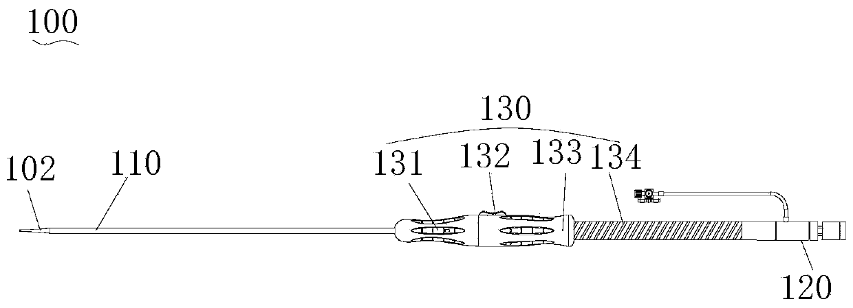
[0044] See figure 1 As shown, the delivery device 100 provided by the present invention includes a delivery sheath 110, an adjustment mechanism 120 and a handle assembly 130.

[0045] The delivery sheath 110 is a hollow tube, and the lumen of the delivery sheath 110 can be loaded with an implant, such as the stent graft 101 (see Figure 4 Shown).

[0046] The distal end of the adjustment mechanism 120 is detachably connected to the stent graft 101 to selectively anchor the stent graft 101 or release the anchor of the stent graft 101.

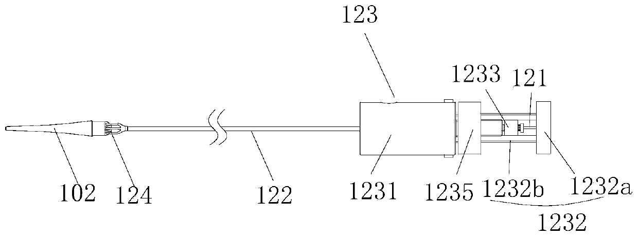
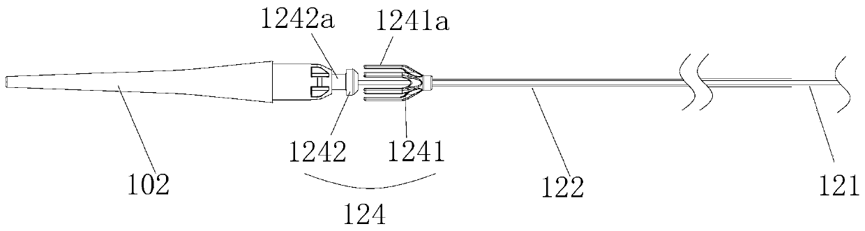
[0047] Combine figure 2 with image 3 As shown, the adjustment mechanism 120 of an embodiment of the present invention includes an inner sheath core tube 121, an outer sheath core tube 122, a control assembly 123, and an anchor assembly 124.

[0048] The outer sheath core tube 122 is sleeved outside the inner sheath core tube 121 and can move axially relative to the inner sheath core tube 121. The control assembly 123 is arranged at the proximal end of...

Embodiment 2

[0110] Combine Figure 15 to Figure 16 As shown, the delivery device 200 of Embodiment 2 also includes a delivery sheath 210, an adjustment mechanism 220, and a handle assembly 230. The structure of the delivery sheath 210 and the handle assembly 230 is similar to that of the first embodiment. The handle assembly 230 includes a front handle 231, a trigger 232, a sliding handle 233 and a screw 234. The mechanism of the handle assembly 230 can be seen in the first embodiment. The handle assembly 130 is not described in detail here.

[0111] The difference between Embodiment 2 and Embodiment 1 is that the structure of the control assembly 223 of the adjustment mechanism 220 is different. Specifically, the first moving part 2232 and the second moving part 2233 of the control assembly 223 have different structural forms relative to the handle body 2231.

[0112] Specifically, combine Figure 17 with Figure 18 As shown, the proximal end of the handle body 2231 is fixedly connected wit...


PUM


Abstract

The invention relates to a conveying device and a control assembly thereof. The control assembly comprises a handle main body, a first moving part and a second moving part, and an inner sheath core tube and an outer sheath core tube can axially and movably penetrate through the handle main body; the first moving part is used for being connected to the inner sheath core tube and controlling the inner sheath core tube to axially move relative to the handle main body, and the first moving part has a locking state or an unlocking state relative to the handle main body; and the second moving part is used for being connected to the outer sheath core tube and controlling the outer sheath core tube to move axially relative to the handle body. According to the conveying device and the control assembly thereof, the inner sheath core tube and the outer sheath core tube are controllably controlled by the control assembly to move in the axial direction. Under the condition that a covered stent is anchored by an anchoring assembly, the far end of the covered stent is synchronously pulled to move towards the near end, so that the far end of the membrane of the covered stent is attached to the blood vessel wall, axial deviation of the far end of the membrane of the covered stent before and after released is avoided, and then the release precision of the covered stent is improved.

Description

Technical field [0001] The present invention relates to the technical field of medical devices, in particular to a conveying device and its control assembly. Background technique [0002] Thoracic aortic endovascular repair treatment technology was first proposed by Parodi and used for the treatment of thoracic aortic dilatation diseases, and then gradually used for the treatment of Stanford B aortic dissection (TBAD). Through research and technological improvements in recent years, it has become the preferred treatment for all types of TBAD, including acute, chronic, stable and unstable types, and has basically replaced the traditional open thoracic aortic replacement surgery. Thoracic aortic endovascular repair treatment technology is to seal the primary endometrial rupture through the covered stent, and expand the true cavity, compress the false cavity, promote the thrombosis of the false cavity, prevent the dissection rupture, achieve aortic reconstruction, and improve the di...

Claims


Application Information

Patent Timeline
IPC IPC(8): A61F2/95A61F2/966
CPCA61F2/95A61F2/966
Inventor 浦文俊严新火
Owner LIFETECH SCIENTIFIC (SHENZHEN) CO LTD
Why Eureka
Try Eureka