Crushing pair with sieve frame

A technology of screen frame and crushing cavity, applied in the field of mining machinery, can solve the problems of large floor space, increased manufacturing cost, operating cost and self-consumption power, complex crushing production line, etc., to achieve small floor space and improve screening effect. , the effect of simplifying the device

Inactive Publication Date: 2020-03-27
YIWU MULTI UNION MINING MACHINERY SUPERMARKET
View PDF8 Cites 2 Cited by
  • Summary
  • Abstract
  • Description
  • Claims
  • Application Information

AI Technical Summary

Problems solved by technology

The functions of the two are different, but their structures are similar. In the existing crushing production line, the crusher and the vibrating screen are set independently, and the vibrating screen needs to be equipped with an independent vibrator and power device, which increases the manufacturing cost, operating cost and Self-consumption, and it is necessary to set up a separate conveying device to complete the mineral material conveying between the crusher and the vibrating screen, resulting in the complexity of the entire crushing production line and a large footprint

Method used


Image

  • Crushing pair with sieve frame
  • Crushing pair with sieve frame
  • Crushing pair with sieve frame

Examples


Embodiment 1

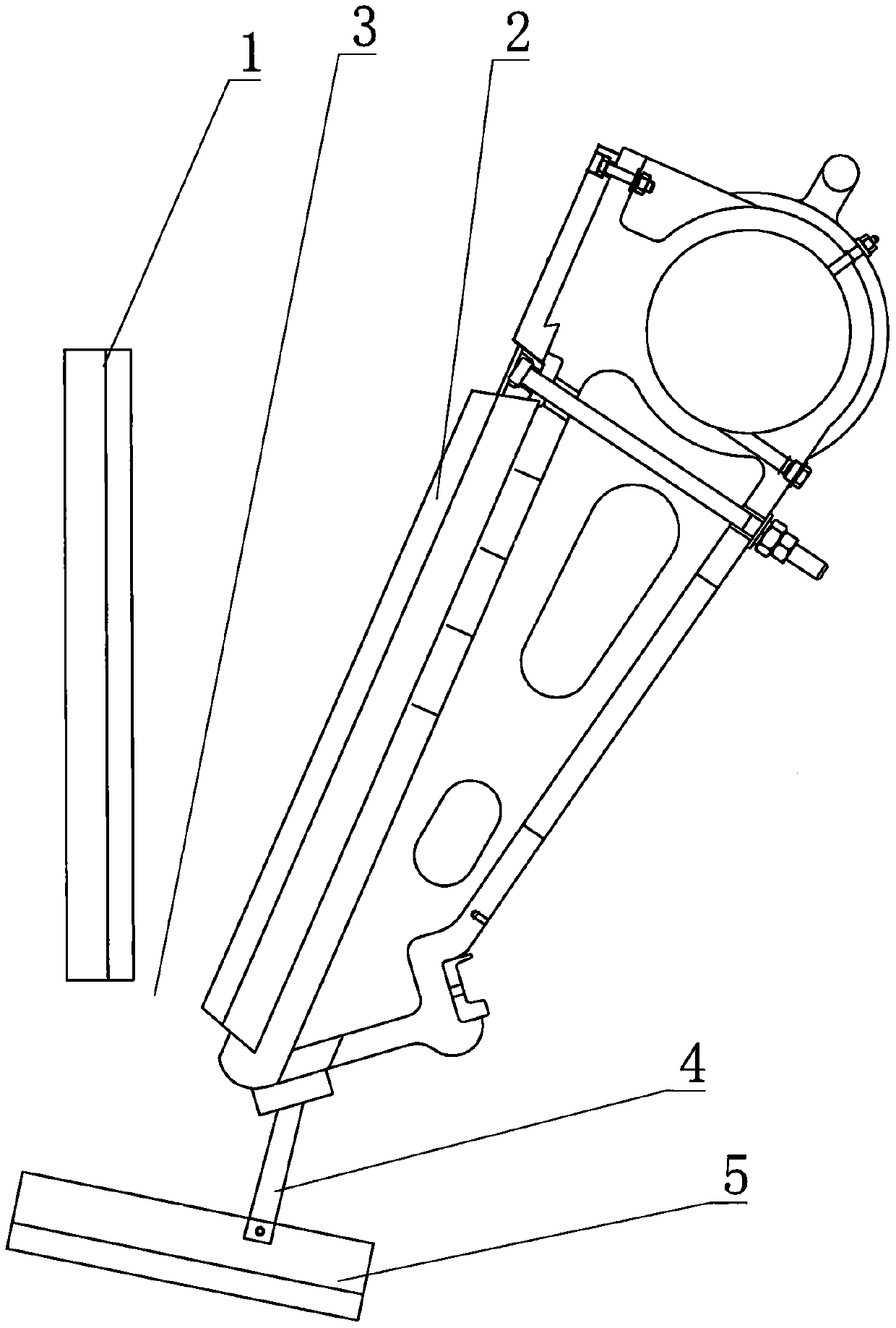
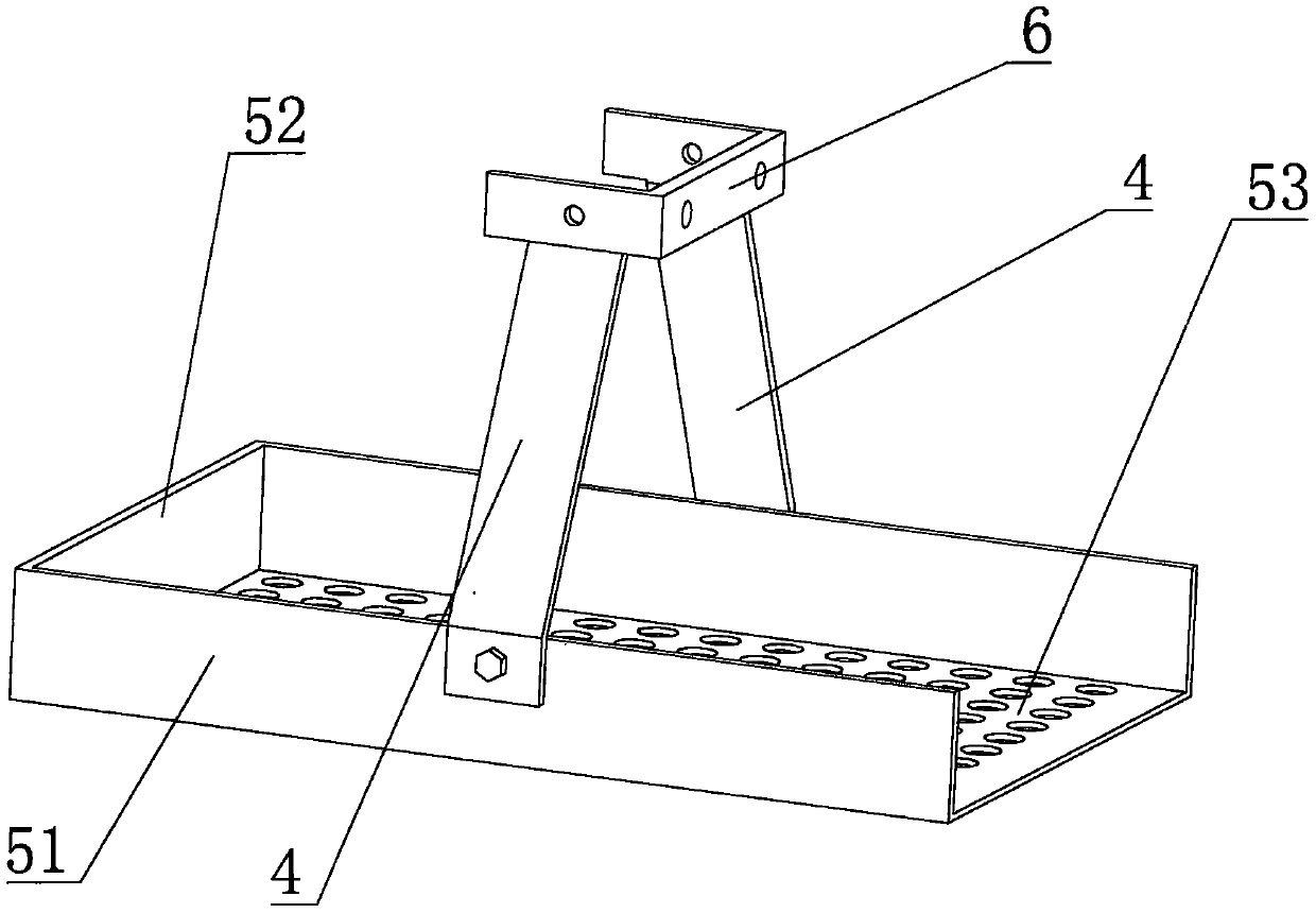
[0030] Embodiment 1: as Figure 1-3 As shown, a crushing pair with a screen frame includes a fixed jaw 1 and a movable jaw 2, a crushing cavity is formed between the fixed jaw 1 and the movable jaw 2, and the movable jaw 2 is driven by a driving device to approach or move away from the fixed jaw Jaw 1 crushes materials, and the bottom of the crushing cavity is provided with a discharge port 3; the lower part of the movable jaw 2 is equipped with a connecting arm 4, and a screen frame 5 is installed at the lower end of the connecting arm 4, and the screen frame 5 is located at the discharge port 3 Below; there are two connecting arms 4, the lower ends of which are respectively symmetrically installed on the two side plates 51 of the screen frame through high-strength bolts, and the upper ends are connected together by a U-shaped mounting part 6, and the U-shaped mounting part 6 and the two The root connecting arm 4 is integrally formed, and the U-shaped mounting part 6 is provi...

Embodiment 2

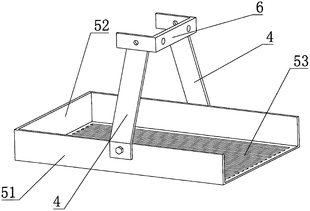
[0031] Embodiment 2: as image 3 As shown, the difference from Example 1 is that a double-layer sieve plate is arranged in the screen frame 5, and the two layers of sieve plates are parallel to each other, and are arranged in the screen frame from top to bottom. Defined as the first sieve plate 531 and the second sieve plate 532, the first sieve plate 531 is a sieve bar structure, the second sieve plate 532 is a screen mesh structure, and the screening gap of the first sieve plate 531 is larger than that of the second sieve plate 532 In the screening gap, after the mineral material is crushed by the crushing pair, it falls from the discharge port 3 onto the first sieve plate 531 of the screen frame 5, and the screen frame 5 moves with the movable jaw 2 to screen the mineral material. Mineral materials larger than the screening gap of the first sieve plate 531 are discharged from the corresponding discharge port, and mineral materials with a particle size smaller than the scree...


PUM


Abstract

The invention provides a crushing pair with a sieve frame, and belongs to the technical field of mining machinery. The crushing pair includes a fixed jaw and a movable jaw. A crushing cavity is formedbetween the fixed jaw and the movable jaw. The movable jaw gets close to or away from the fixed jaw under the driving of a driving device to crush ore material. The bottom of the crushing cavity is provided with a discharge port. A connecting arm is installed at the lower part of the movable jaw. The sieve frame is installed at the lower end of the connecting arm, is located below the discharge port, and capable of receiving the ore material falling from the crushing cavity. In the invention, the sieve frame is directly installed at the lower part of the movable jaw, and the sieving can be completed without an additional power device, which reduces the manufacturing and operating costs of the crushing pair and simplifies a crushing production line.

Description

technical field [0001] The invention belongs to the technical field of mining machinery, in particular to a crushing pair with a screen frame. Background technique [0002] Crushing and screening are two of the most basic and common operations in the field of mining machinery. Crushing and screening have a common structural feature, that is, they all contain an eccentrically arranged main shaft, which is called "eccentric shaft" in crushing equipment. ", called "exciting shaft" in the screening equipment, the crushing pair is the most important component of the jaw crusher, which crushes the mineral material driven by the eccentric shaft. The function of the eccentric shaft in the crusher is to make the crusher produce a crushing stroke, thereby effectively crushing; the function of the exciting shaft is to make the vibrating screen generate an exciting force, thereby effectively screening. The functions of the two are different, but their structures are similar. In the exi...

Claims


Application Information

Patent Timeline
Patent Type & Authority Applications(China)
IPC IPC(8): B02C1/04B02C23/00B02C23/14
CPCB02C1/04B02C23/00B02C23/14
Inventor 朱兴良
Owner YIWU MULTI UNION MINING MACHINERY SUPERMARKET
Why Eureka
Try Eureka