Stamping part inspection device

A technology of inspection devices and stamping parts, applied in metal processing, metal processing equipment, manufacturing tools, etc., can solve the problems of low manual detection efficiency, achieve the effect of improving visual detection effect, increasing production efficiency, and reducing manual operation

Inactive Publication Date: 2020-03-27
安徽戎发冲压机器人有限公司
View PDF9 Cites 0 Cited by
  • Summary
  • Abstract
  • Description
  • Claims
  • Application Information

AI Technical Summary

Problems solved by technology

[0003] The purpose of the present invention is to provide a stamping parts inspection device, the stamping parts are transferred to the inspection table through the feeding conveyor belt, the pushing mechanism pushes the stamping parts to the workbench, and the visual detection camera performs visual inspection on the stamping parts, and passes through The left jacking cylinder and the right jacking cylinder respectively jack up the workbench to make the qualified and unqualified stamping parts slide on the left and right feeding conveyors respectively, which solves the problem of low efficiency of manual inspection

Method used


Image

  • Stamping part inspection device
  • Stamping part inspection device

Examples


Embodiment Construction

[0013] In order to deepen the understanding of the present invention, the present invention will be further described below in conjunction with examples, which are only used to explain the present invention and do not constitute a limitation to the protection scope of the present invention.

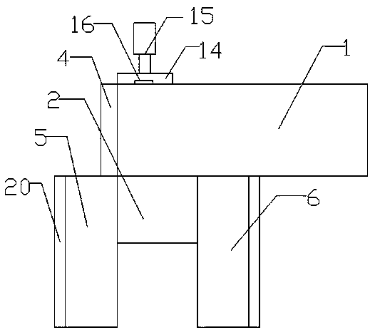
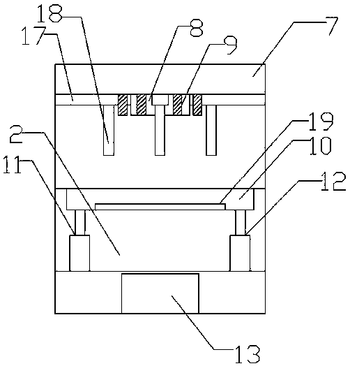
[0014] like figure 1 As shown, this embodiment provides a stamping inspection device, including a feeding conveyor belt 1 and a detection platform 2, the detection platform 2 is arranged on the front side of the left end of the feeding conveyor belt 1, and the detection platform 2 is provided on the rear side of the left end of the feeding conveyor belt 1. Pushing mechanism, the left end of the feeding conveyor belt 1 is provided with a material blocking plate 4, the left side of the detection platform 2 is provided with a left lower material conveyor belt 5, the right side of the detection platform 2 is provided with a right lower material conveyor belt 6, and a bracket is provided above ...


PUM


Abstract

The invention provides a stamping part inspection device. The stamping part inspection device comprises a feeding conveying belt and a detecting table. The detecting table is arranged on the front side of the left end of the feeding conveying belt, and a pushing mechanism is arranged at the position, corresponding to the detecting table, of the rear side of the left end of the feeding conveying belt. A striker plate is arranged at the left end of the feeding conveying belt, and a left discharging conveying belt is arranged on the left side of the detecting table. A right discharging conveyingbelt is arranged on the right side of the detecting table. A support is arranged above the detecting table, and a visual detecting camera is arranged in the middle of the lower surface of the support.An illuminating lamp is arranged on the periphery of the visual detecting camera, and a workbench is arranged on the detecting table. The left end and the right end of the lower side of the workbenchare connected with a left jacking air cylinder and a right jacking air cylinder through hinges correspondingly. A controller is arranged on the detecting table. By means of conveying of the feeding conveying belt, a stamping part is pushed to the workbench through the pushing mechanism, visual detecting camera carries out visual detection, and the workbench is jacked for sorting and conveying through the left jacking air cylinder and the right jacking air cylinder; and the structure is simple, and the detecting efficiency is effectively improved.

Description

technical field [0001] The invention relates to the field of stamping parts inspection equipment, in particular to a stamping parts inspection device. Background technique [0002] Thermoforming stamping equipment forms stamping parts after stamping materials. Stamping parts need to be inspected after stamping. The existing manual inspection method is used, the inspection efficiency is low, and there are errors. Therefore, it becomes very difficult to solve this problem. important. Contents of the invention [0003] The purpose of the present invention is to provide a stamping parts inspection device, the stamping parts are transferred to the inspection table through the feeding conveyor belt, the pushing mechanism pushes the stamping parts to the workbench, and the visual detection camera performs visual inspection on the stamping parts, and passes through The left jacking cylinder and the right jacking cylinder respectively jack up the workbench to make the qualified an...

Claims


Application Information

Patent Timeline
Patent Type & Authority Applications(China)
IPC IPC(8): B21C51/00
CPCB21C51/00
Inventor 戴广文韩兴明
Owner 安徽戎发冲压机器人有限公司
Why Eureka
Try Eureka