Bending device

The technology of a bending device and a flat needle is applied in the field of bending devices, which can solve the problems of inconvenient connection and difficult bending process of the bending device, and achieve the effect of avoiding breakage.

Pending Publication Date: 2020-03-27
DONGGUAN WORLD PRECISION MACHINERY
View PDF0 Cites 1 Cited by
  • Summary
  • Abstract
  • Description
  • Claims
  • Application Information

AI Technical Summary

Problems solved by technology

[0003] Although FPC has the advantages of thinness, small space, and adaptability to different space occasions, the flexible material of FPC flexible cable also causes the problem of inconvenient connection. It is necessary to pre-size the flexible cable according to the applicable environment to facilitate the installation of electronic products. to assemble
[0004] In the FPC flexible cable, it is necessary to bend the FPC flexible cable 180 degrees, please refer to the attached manual Figure 1 to Figure 2 , the FPC flexible cable 200 includes a first elongated board 210 , a second elongated board 220 and an arc bending portion 230 , and the arc bending portion 230 is located between the first elongated board 210 and the second elongated board 220 , in actual processing, it is necessary to bend the second elongated plate 220 toward the first elongated plate 210, and the first elongated plate 210 and the second elongated plate 220 are attached to each other after bending. The bending position between the first elongated plate 210 and the second elongated plate 220 is broken, and the arc bending part 230 needs to be bent into an arc shape. However, it is difficult for the existing bending devices to automatically complete the above bending. bending process, so it cannot meet the existing production demand

Method used


Image

  • Bending device
  • Bending device
  • Bending device

Examples


Embodiment Construction

[0028] In order to describe the technical content and structural features of the present invention in detail, further description will be given below in conjunction with the implementation and accompanying drawings.

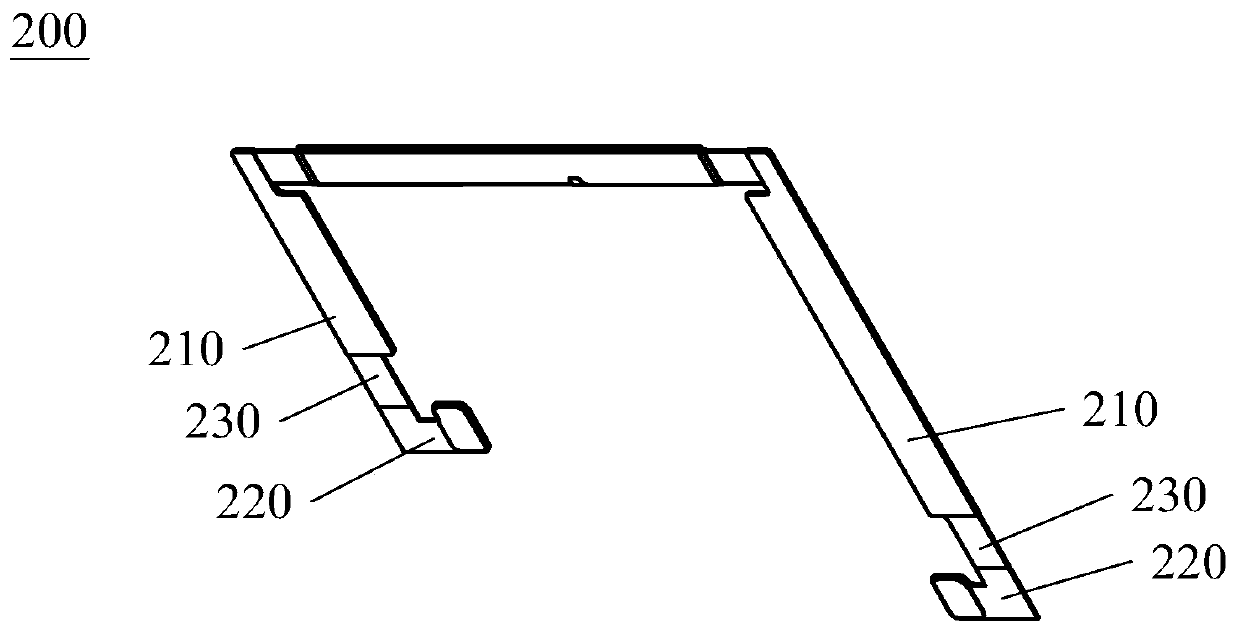
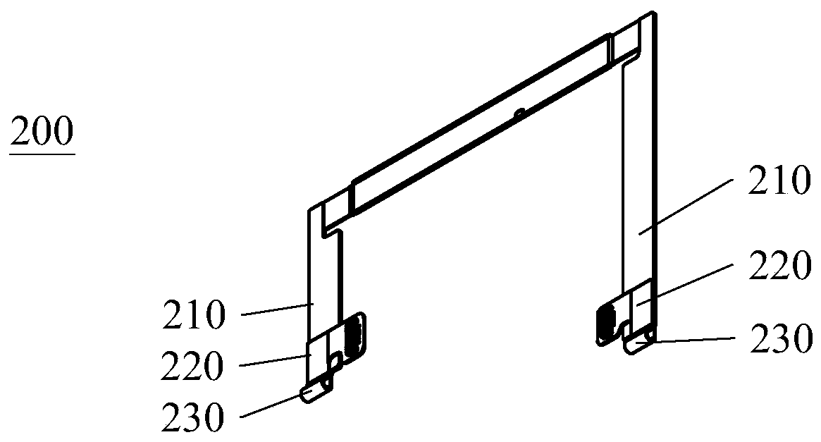
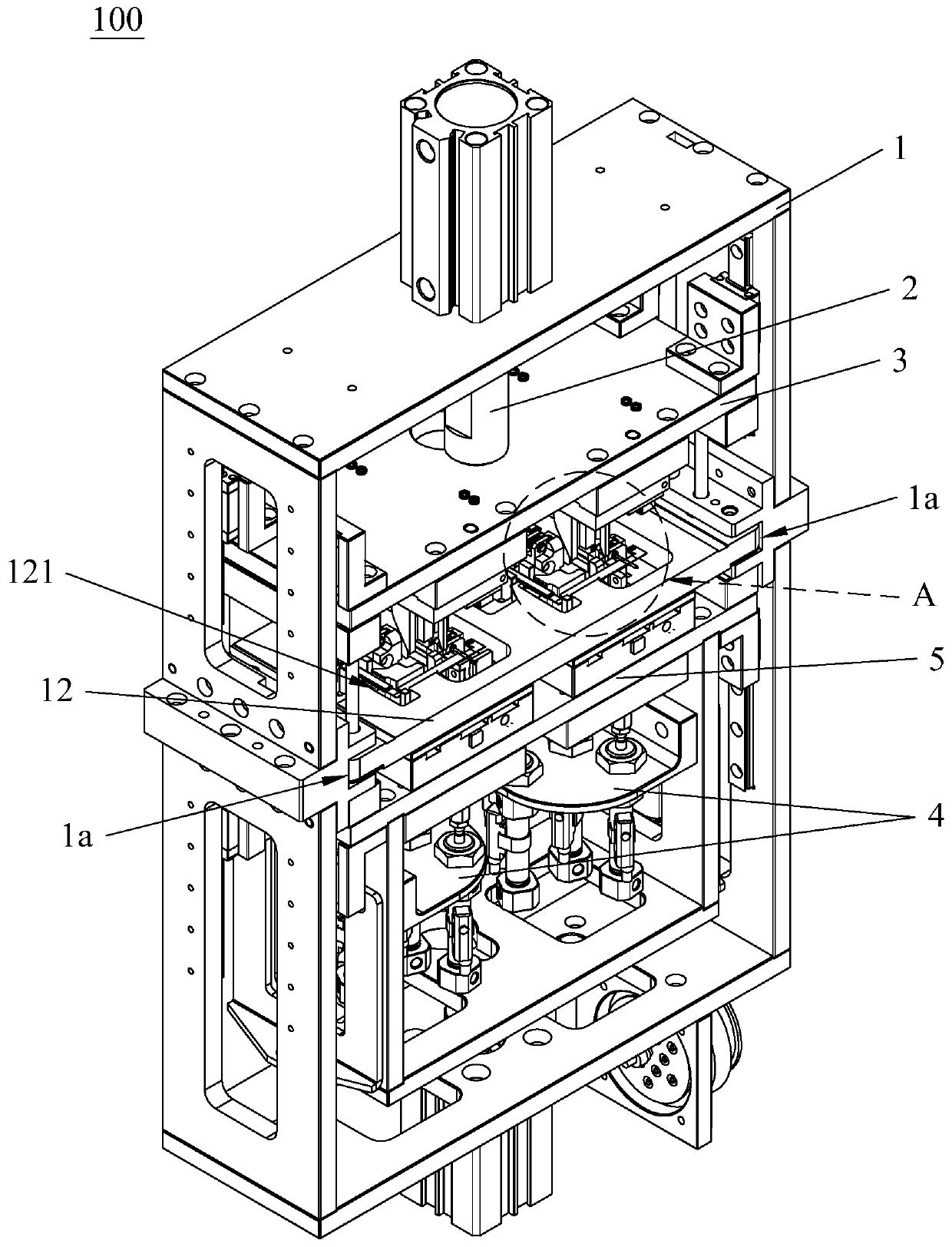
[0029] The present invention provides a bending device 100, which is used for 180-degree bending of a workpiece 200, please refer to the attached Figure 1 to Figure 2 , the workpiece 200 includes a first elongated plate 210, a second elongated plate 220 and an arc bending portion 230, the arc bending portion 230 is located between the first elongated plate 210 and the second elongated plate 220, and the second The elongated plate 220 is bent toward the first elongated plate 210, and the first elongated plate 210 and the second elongated plate 220 are attached to each other after bending, in order to avoid the first elongated plate 210 and the second elongated plate The bending position between 220 is broken, and the arc bending part 230 needs to be bent into an a...


PUM


Abstract

The invention discloses a bending device comprising a rack, an upper die, a lower die, a locating assembly, a flat needle assembly, a push part, a pressing assembly, a bending assembly, a jacking block and a carrier. The lower die rises to have a lower die first position and a lower die second position relative to the carrier. The upper die is installed on the rack in a rising and falling mode. The upper die falls to have an upper die first position and an upper die second position relative to the carrier. The locating assembly is installed on the lower die. The flat needle assembly is slidably arranged in the lower die. Both the push part and the pressing assembly are installed on the upper die. The push part pushes a flat needle of the flat needle assembly to move. When the upper die islocated in the upper die first position, the flat needle extends into the bent position of a workpiece, and the pressing assembly tightly presses the workpiece on the carrier. The bending assembly isinstalled on the upper die and comprises a bending driving assembly and a bending gear. The jacking block is installed on the lower die. Through the bending device, 180-degree bending of the workpiececan be completed automatically, and the bending device has the advantages of being high in automation degree, high in product precision and the like.

Description

technical field [0001] The invention relates to the field of electronic component processing, in particular to a bending device. Background technique [0002] In electronic products, FPC is usually used to realize power supply and communication connection between different electronic components: the electronic component is provided with an FPC electrically connected to it, and the FPC extends out of the electronic component to connect to the electrical connection part of another component. [0003] Although FPC has the advantages of thinness, small space, and adaptability to different space occasions, the flexible material of FPC flexible cable also causes the problem of inconvenient connection. It is necessary to pre-size the flexible cable according to the applicable environment to facilitate the installation of electronic products. Assemble. [0004] In the FPC flexible cable, it is necessary to bend the FPC flexible cable 180 degrees, please refer to the attached manual...

Claims


Application Information

Patent Timeline
Patent Type & Authority Applications(China)
IPC IPC(8): B21D11/10
CPCB21D11/10
Inventor 吴海洋申宇
Owner DONGGUAN WORLD PRECISION MACHINERY
Why Eureka
Try Eureka