
Hardware stamping die with stamping head convenient to replace

A technology of stamping die and stamping head, applied in the field of metal stamping dies which is easy to replace the stamping head, can solve the problems of affecting the stamping quality of stamping parts, reducing the stamping efficiency of workpieces, discount of stamping quality of workpieces, etc., to achieve reasonable structural design and ensure stamping quality. , to ensure the effect of stability

Inactive Publication Date: 2020-03-27
吴中区甪直磊鑫模具厂
View PDF0 Cites 3 Cited by
  • Summary
  • Abstract
  • Description
  • Claims
  • Application Information

AI Technical Summary

Problems solved by technology

[0002] Metal stamping die is a machine for stamping and producing sheet metal parts. It has the advantages of high production efficiency and short production cycle. The stamping head realizes continuous work, but the stamping head is prone to wear after long-term use. The worn stamping head greatly reduces the stamping quality of the workpiece and seriously affects the stamping quality of the stamping parts. Moreover, when the existing stamping die is working, the stamping head Once damaged after working for a long time, it is inconvenient to replace and troublesome to disassemble, which greatly reduces the stamping efficiency of the workpiece. Therefore, we propose a metal stamping die that is easy to replace the stamping head

Method used


Image

  • Hardware stamping die with stamping head convenient to replace
  • Hardware stamping die with stamping head convenient to replace
  • Hardware stamping die with stamping head convenient to replace

Examples


Embodiment Construction

[0015] The following will clearly and completely describe the technical solutions in the embodiments of the present invention with reference to the accompanying drawings in the embodiments of the present invention. Obviously, the described embodiments are only some, not all, embodiments of the present invention. Based on the embodiments of the present invention, all other embodiments obtained by persons of ordinary skill in the art without making creative efforts belong to the protection scope of the present invention.

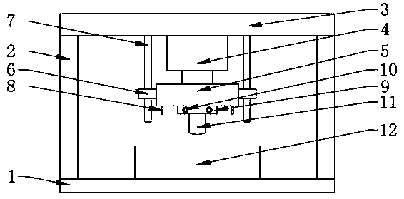
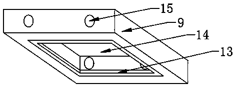
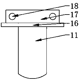
[0016] see figure 1 , figure 2 and image 3 , the present invention provides a technical solution: a metal stamping die for easy replacement of punching heads, including a base 1, brackets 2 are fixedly arranged on the left and right sides of the top of the base 1, and top plates 3 are fixedly installed on the tops of two sets of brackets 2, The center of the bottom of the top plate 3 is fixedly provided with a lifting electric telescopic rod 4, the output ...


PUM


Abstract

The invention discloses a hardware stamping die with a stamping head convenient to replace in the technical field of hardware stamping dies. The left and right sides of the bottom of an upper die areboth fixedly provided with locating columns. A mounting plate is fixedly welded to the bottom center of the upper die. The stamping head is fixedly in screwed connection with the bottom of the mounting plate through fastening bolts. The bottom of the mounting plate is provided with a locating groove. The sidewall of the side, far away from an opening, of the interior of the locating groove is provided with a limiting insertion groove. The front and rear sidewalls of the mounting plate are both provided with corresponding threaded through holes. A limiting plate matched with the locating grooveis fixedly welded to the top of the stamping head. An insertion block matched with the limiting insertion groove is fixedly welded to the top of the limiting plate. The front sidewall of the insertion block is provided with insertion through holes corresponding to the threaded through holes. Through the hardware stamping die with the stamping head convenient to replace, the stamping quality of the stamping head can be ensured; the stamping head can be fast and convenient to replace and dismantle, the hardware stamping die is convenient to operate, and the disassembling and assembling convenience is improved.

Description

technical field [0001] The invention relates to the technical field of metal stamping dies, in particular to a metal stamping die for easy replacement of stamping heads. Background technique [0002] Metal stamping die is a machine for stamping and producing sheet metal parts. It has the advantages of high production efficiency and short production cycle. The stamping head realizes continuous work, but the stamping head is prone to wear after long-term use. The worn stamping head greatly reduces the stamping quality of the workpiece and seriously affects the stamping quality of the stamping parts. Moreover, when the existing stamping die is working, the stamping head Once damaged after working for a long time, it is inconvenient to replace and troublesome to disassemble, which greatly reduces the stamping efficiency of the workpiece. Therefore, we propose a metal stamping die that is easy to replace the stamping head. Contents of the invention [0003] The object of the p...

Claims


Application Information

Patent Timeline
Patent Type & Authority Applications(China)
IPC IPC(8): B21D37/04B21D37/12B21D22/02
CPCB21D22/02B21D37/04B21D37/12
Inventor 陈晓升徐明峰
Owner 吴中区甪直磊鑫模具厂
Learn More