Distributed antenna system

A technology for distributing antennas and transmitting antennas, applied to antennas, antenna arrays, antenna components, etc., can solve the problem of high cost, reduce costs, avoid merger costs, and eliminate energy loss.

Inactive Publication Date: 2004-03-24
ANDREW CORP
View PDF0 Cites 9 Cited by
  • Summary
  • Abstract
  • Description
  • Claims
  • Application Information

AI Technical Summary

Problems solved by technology

[0005] To achieve linearity in a comprehensive system, all the additional circuitry used requires a relatively high output system, which also makes the cost per unit component / electricity relatively high

Method used


Image

  • Distributed antenna system
  • Distributed antenna system
  • Distributed antenna system

Examples


Embodiment Construction

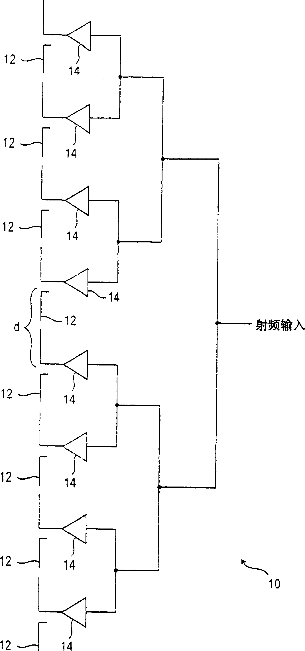
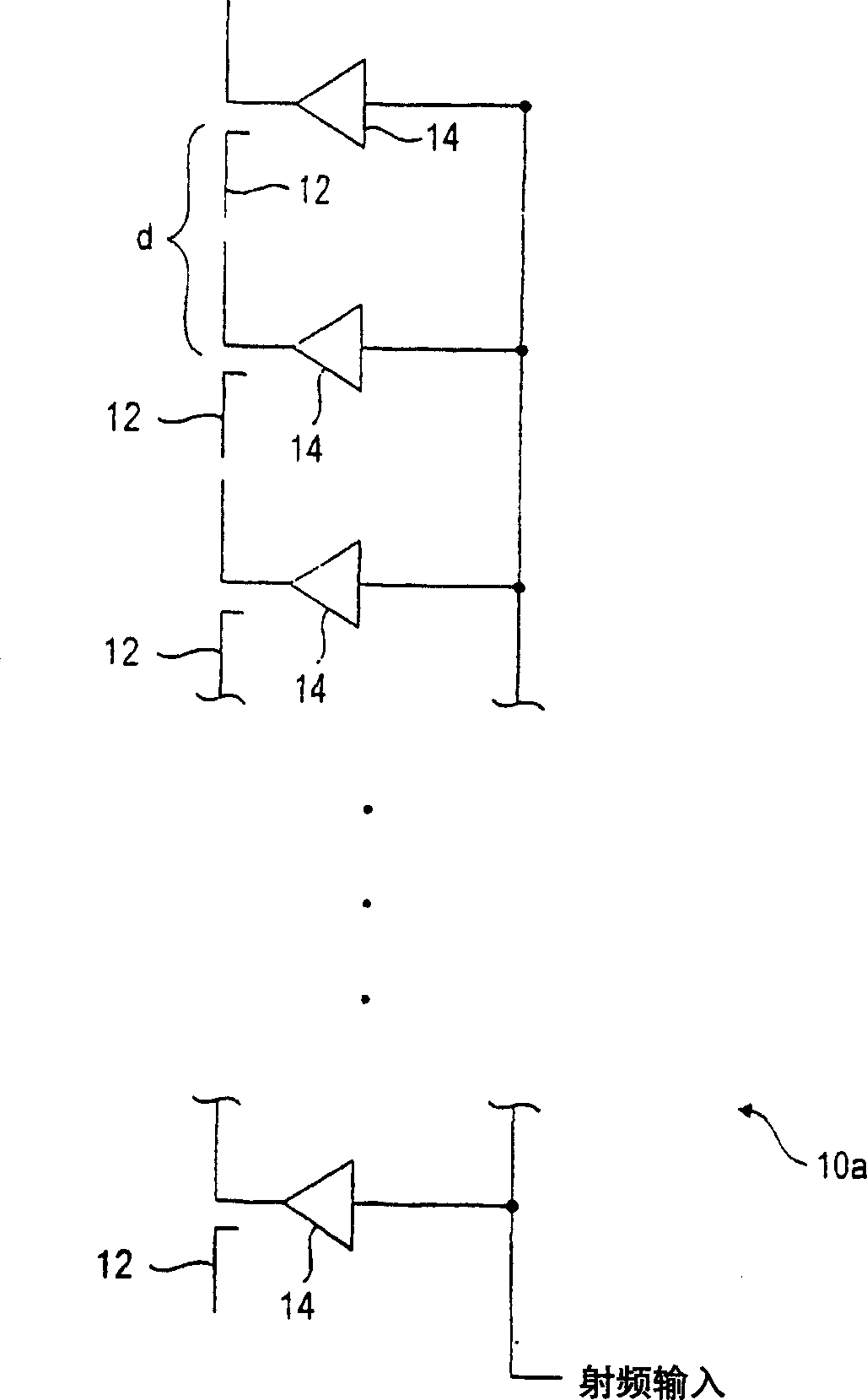
[0033] Referring now to the accompanying drawings, first from figure 1 , 2 In the beginning, two examples of antenna arrays 10, 10a of multiple antenna elements of the present invention are described. figure 1 , 2 The feed structures used by the antenna arrays 10, 10a are different in configuration, figure 1 is to illustrate the parallel common feed structure, figure 2 Is to illustrate the serial common feed structure. In other respects, the two antenna arrays 10, 10a are substantially identical. Each antenna array 10, 10a includes a plurality of antenna elements 12, which may include single-pole, even-pole, or microstrip / patch antenna elements. Other forms of antenna elements may also be used to form the arrays 10, 10a without departing from the invention.

[0034] According to an aspect of the present invention, a multi-carrier linear amplifier 14 is connected to the feed point of each antenna element 12 and is mounted adjacent to that antenna element 12 . In one emb...


PUM


Abstract

A distributed antenna device includes a plurality of transmit antenna elements (12), a plurality of receive antenna elements (30) and a plurality of amplifiers (14, 140). One of the amplifiers (14) is a relatively low power, linear amplifier operatively coupled with each of the transmit antenna elements (12) and mounted closely adjacent to the associated transmit antenna element (12), such that no appreciable power loss occurs between the power amplifier (14) and the associated antenna element (12). At least one of the amplifiers (140) is a low noise amplifier and is built into the distributed antenna device for receiving and amplifying signals from at least one of the receive antenna device for receiving and amplifying signals from at least one of the receive antenna elements (30).

Description

technical field [0001] The present invention relates generally to active antennas, and more particularly to integrated active antennas for multi-carrier applications. The present invention also relates to novel antenna structures and systems comprising antenna arrays that can be used for both transmit (Tx) and receive (Rx) operations. Background technique [0002] In communications equipment such as cellular equipment, Personal Communications Services (PCS), Multichannel Multipoint Distribution Systems (MMDS), and Local Multipoint Distribution Systems (LMDS), antennas mounted on top of towers or other structures are commonly used to receive and re- Transmitting a signal from a user or user. Other communication systems, such as wireless local loop (WLL), private mobile radio (SMR), and wireless local area network (WLAN), have an infrastructure for transmitting signals that are received and retransmitted between users or users of the system For communication, users can also ...

Claims


Application Information

Patent Timeline
Patent Type & Authority Applications(China)
IPC IPC(8): H01Q1/24H01Q3/28H01Q21/08H01Q23/00
CPCH01Q1/246H01Q21/08H01Q3/28H01Q23/00
Inventor 迈克・托马斯马诺・D・贾德托马斯・D・蒙特唐纳德・G・雅克松格雷戈里・A・马卡
Owner ANDREW CORP
Why Eureka
Try Eureka