Method for controlling a hydraulic system of a working machine

a technology of working machine and hydraulic system, which is applied in the direction of mechanical machines/dredgers, couplings, mechanical apparatus, etc., can solve problems such as energy loss, and achieve the effect of reducing energy loss

Active Publication Date: 2013-08-15
VOLVO CONSTR EQUIP
View PDF5 Cites 2 Cited by
  • Summary
  • Abstract
  • Description
  • Claims
  • Application Information

AI Technical Summary

Benefits of technology

[0009]An object of the invention is to provide a method defined by way of introduction, by

Problems solved by technology

Since a hydraulic system always has some leakages a maximal pump pressure will in addition to unnecessary load and wear lead to energy l

Method used


Image

  • Method for controlling a hydraulic system of a working machine
  • Method for controlling a hydraulic system of a working machine
  • Method for controlling a hydraulic system of a working machine

Examples


Embodiment Construction

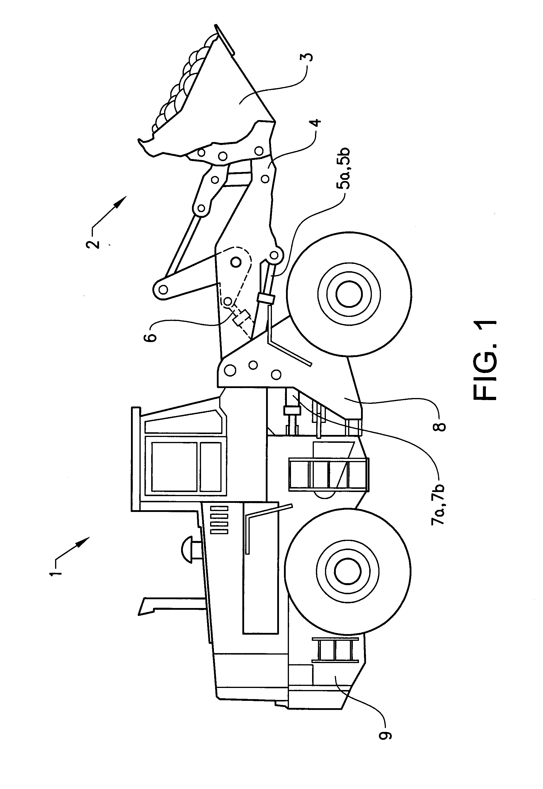
[0020]FIG. 1 is an illustration of a working machine 1 in the form of a wheel loader having an implement 2. The term “implement” is intended to comprise any kind of tool using hydraulics, such as a bucket, a fork or a gripping tool arranged on a wheel loader, or a container arranged on an articulated hauler. The implement illustrated is a bucket 3 which is arranged on an arm unit 4 for lifting and lowering the bucket 3, and further the bucket 3 can be tilted relative to the arm unit 4. The wheel loader 1 is provided with a hydraulic system comprising at least one hydraulic machine (not shown in FIG. 1). The hydraulic machine can be a hydraulic pump, although it is preferred that the hydraulic machine can work as a hydraulic pump as well as a hydraulic motor with a reversed flow of hydraulic fluid. Such a hydraulic machine with said both functions can be used as a pump for providing the hydraulic system with hydraulic fluid, for example to lift and tilt the bucket, and as a hydraulic...


PUM


Abstract

A method is provided for controlling a hydraulic system of a working machine. The hydraulic system includes a hydraulic machine for providing hydraulic fluid to one or more actuators of the working machine. The method includes receiving a signal requesting a pump pressure from the hydraulic machine based on the load pressure of a first actuator of the one or more actuators which first actuator has the highest load pressure of the one or more actuators, discriminating the pressure request from the first actuator provided that the first actuator is stalled due to overload or geometrical limitations, and controlling the hydraulic machine to provide to pump pressure based on the load pressure of a second actuator of the one or more actuators which second actuator is in operation and has the second highest load pressure of the one or more actuators, or, if no actuator in addition to the first actuator is present and in operation, controlling the hydraulic machine to provide a predetermined idle pump pressure.

Description

TECHNICAL FIELD[0001]The invention relates to a method for controlling a hydraulic system of a working machine according to the preamble of claim 1.[0002]The invention is applicable on working machines within the fields of industrial construction machines, in particular wheel loaders. Although the invention will be described hereinafter with respect to a wheel loader, the invention is not restricted to this particular machine, but may also be used in other heavy working machines, such as articulated haulers, dump trucks, graders, excavators or other construction equipment.BACKGROUND OF THE INVENTION[0003]A working machine is provided with a bucket, container or other type of implement for digging, lifting, carrying and / or transporting a load.[0004]For example, a wheel loader has a load arm unit for raising and lowering an implement, such as a bucket. The load arm unit comprises a number of hydraulic cylinders for movement of a load arm and the implement attached to the load arm. A p...

Claims


Application Information

Patent Timeline
IPC IPC(8): F15B15/18
CPCE02F9/2235F15B15/18F15B11/165F15B2211/20546F15B2211/251F15B2211/6309F15B2211/6313F15B2211/633F15B2211/665F15B2211/6652F15B2211/6653F15B2211/71F15B2211/781F15B2211/88E02F9/2296E02F3/43E02F9/22F15B11/16
Inventor VIGHOLM, BOKARLSSON, JANEKVALL, ANDREASHEYBROEK, KIM
Owner VOLVO CONSTR EQUIP
Why Eureka
Try Eureka