High-efficiency cycloidal-pin wheel speed reducer with sensor

A pin-wheel reducer and sensor technology, applied to components with teeth, belts/chains/gears, transmission boxes, etc., can solve the problems of reducing transmission efficiency and improving reducers, so as to eliminate energy loss and high reliability , The effect of high transmission efficiency

Pending Publication Date: 2022-04-15
扬州星辰制造技术有限公司
View PDF0 Cites 2 Cited by
  • Summary
  • Abstract
  • Description
  • Claims
  • Application Information

AI Technical Summary

Problems solved by technology

At the same time, most of the cycloidal pinwheel reducers on the domestic and foreign markets currently use two or more cycloidal wheels for transmission. The cycloidal wheels are supported on the crank shaft through roller bearings, but multiple cycloidal wheels There is no restricted position in the axial direction. Due to manufacturing errors, the cycloidal wheels may move axially during the working process, resulting in surface-to-surface friction on the end faces of the two cycloidal wheels. Especially under certain loads, it will increase the friction in the reducer. temperature, reducing transmission efficiency

Method used


Image

  • High-efficiency cycloidal-pin wheel speed reducer with sensor
  • High-efficiency cycloidal-pin wheel speed reducer with sensor
  • High-efficiency cycloidal-pin wheel speed reducer with sensor

Examples


Embodiment Construction

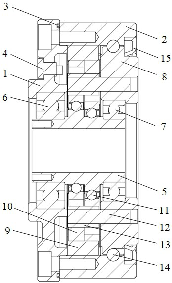
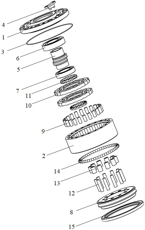
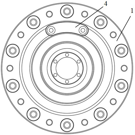
[0018] like Figure 1-Figure 4 As shown, this specific embodiment adopts the following technical scheme: it includes a support end 1, a pin gear housing 2, a sealing ring 3, a sensor 4, a crankshaft 5, a first standard ball bearing 6, a second standard ball bearing 7, an output End 8, needle roller 9, cycloid wheel 10, first non-standard ball bearing 11, cylindrical pin 12, column pin sleeve 13, second non-standard ball bearing 14, rotating skeleton oil seal 15. Wherein the support end 1 is fixedly connected with the pin gear housing 2 and a sealing ring 3 is installed on the connection surface, a sensor 4 is installed on the support end 1, and the two ends of the crankshaft 5 are respectively supported by a first standard ball bearing 6 and a second standard ball bearing 7 Supported on the support end 1 and the output end 8, a number of needle rollers 9 are placed in the pin gear housing 2, and the two cycloidal wheels 10 are respectively supported on the eccentric shaft sect...


PUM


Abstract

A supporting end is fixedly connected with a pin wheel housing, a sealing ring is installed on the connecting face, the sensor is installed on the supporting end, and the two ends of a crankshaft are supported on the supporting end and an output end through a first standard ball bearing and a second standard ball bearing respectively. A plurality of roller pins are placed in the pin wheel housing, the two cycloidal gears are supported on the eccentric shaft section of the crankshaft through the two sets of first non-standard ball bearings respectively, a certain gap is reserved between the two end faces in the meshing movement process of the two cycloidal gears and the roller pins, the multiple cylindrical pins are fixedly installed at the output end, and a cylindrical pin sleeve is installed outside each cylindrical pin. Each pin sleeve penetrates through the through holes in the two cycloidal gears at the same time and is matched with the through holes, the output end and the pin wheel housing are supported through a second non-standard ball bearing, and a rotary framework oil seal is installed between the output end and the pin wheel housing. The speed reducer has the advantages of being compact in structure, high in transmission efficiency and high in reliability, and the built-in sensor can collect information of temperature and vibration in the speed reducer.

Description

technical field [0001] The invention relates to the field of mechanical transmission, in particular to a high-efficiency cycloid reducer with sensors. Background technique [0002] Cycloidal pin gear reducers are usually used in robotics, high-end CNC machine tools, medical equipment and other fields. The internal temperature change and vibration of the reducer during use are important indicators for the fault diagnosis and performance evaluation of the reducer. [0003] At present, among the mass-produced cycloid reducer products in the domestic and foreign markets, there are still products with built-in sensors. Through the built-in temperature and vibration sensor, by monitoring the temperature change and vibration data in the reducer, combined with the lubrication conditions, load change conditions and bearing working conditions in the reducer, the fault diagnosis of the reducer can be carried out, and it can be judged whether it is necessary to replace the grease or re...

Claims


Application Information

Patent Timeline
Patent Type & Authority Applications(China)
IPC IPC(8): F16H1/32F16H57/01F16H57/02F16H57/021F16H57/023F16H57/08
Inventor 王心成
Owner 扬州星辰制造技术有限公司
Why Eureka
Try Eureka