Eureka AIR delivers breakthrough ideas for toughest innovation challenges, trusted by R&D personnel around the world.

Lens holder driving device and portable device

A driving device and lens holder technology, applied in electromechanical devices, focusing devices, installation, etc., to achieve the effect of ensuring linearity

Active Publication Date: 2014-05-14
MITSUMI ELECTRIC CO LTD
View PDF5 Cites 9 Cited by
  • Summary
  • Abstract
  • Description
  • Claims
  • Application Information

AI Technical Summary

Problems solved by technology

[0012] However, the inventors of the present invention have noticed that when the lens holder is moved to the vicinity of the maximum stroke by flowing a current to the drive coil, the following problems (problems) occur.

Method used


Image

  • Lens holder driving device and portable device
  • Lens holder driving device and portable device
  • Lens holder driving device and portable device

Examples


no. 1 approach )

[0057] Embodiments of the present invention will be described below with reference to the drawings.

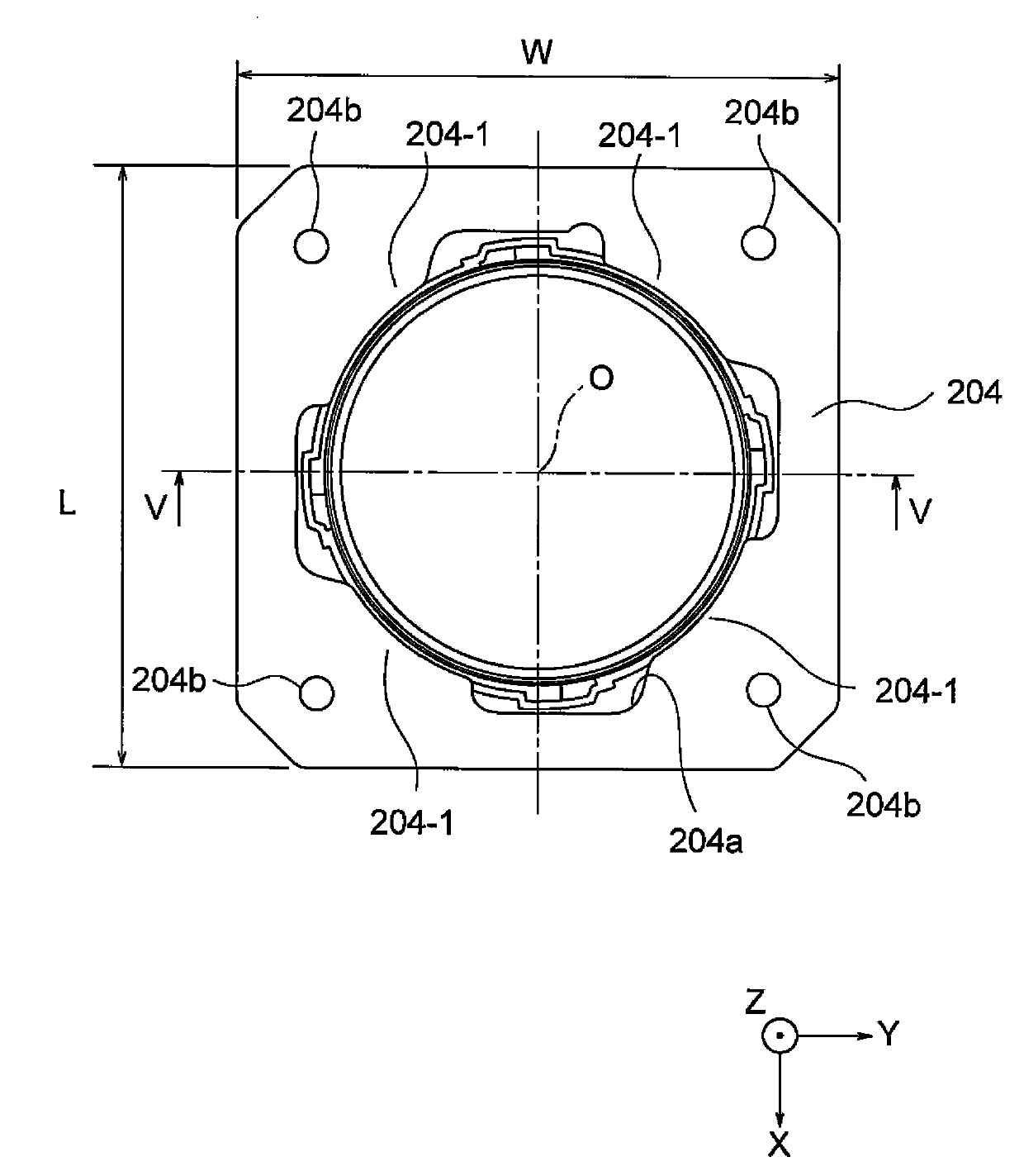
[0058] refer to Figure 3 to Figure 6 The lens holder driving device 10 according to the first embodiment of the present invention will be described. image 3 is a plan view showing the lens holder driving device 10, Figure 4 It is a right side view of the lens holder driving device 10 . Figure 5 its about image 3 Sectional view of the line V-V. Figure 6 It is an exploded perspective view of the lens holder driving device 10 .

[0059] Here, if Figure 3 to Figure 6 As shown, a Cartesian coordinate system (X, Y, Z) is used. exist Figure 3 to Figure 6 In the illustrated state, in the Cartesian coordinate system (X, Y, Z), the X-axis is the front-back direction (depth direction), the Y-axis is the left-right direction (width direction), and the Z-axis is the up-down direction (height direction). and, in Figure 3 to Figure 6 In the example shown, the up-down direct...

no. 2 approach )

[0100] In the lens holder driving device 10 of the first embodiment described above, without changing the material of the lens holder 14, the creases 146a are formed on the upper surface of the holder upper side protrusion 146 to reduce the contact area.

[0101] In contrast, in the lens holder driving device according to the second embodiment of the present invention, the material of the lens holder 14 is also changed. That is, as a molding material of the lens holder 14, a molding material containing conductive carbon (conductive carbon) is used. Thus, the volume resistivity of the lens holder 14 is 1×10 11 [Ω·cm].

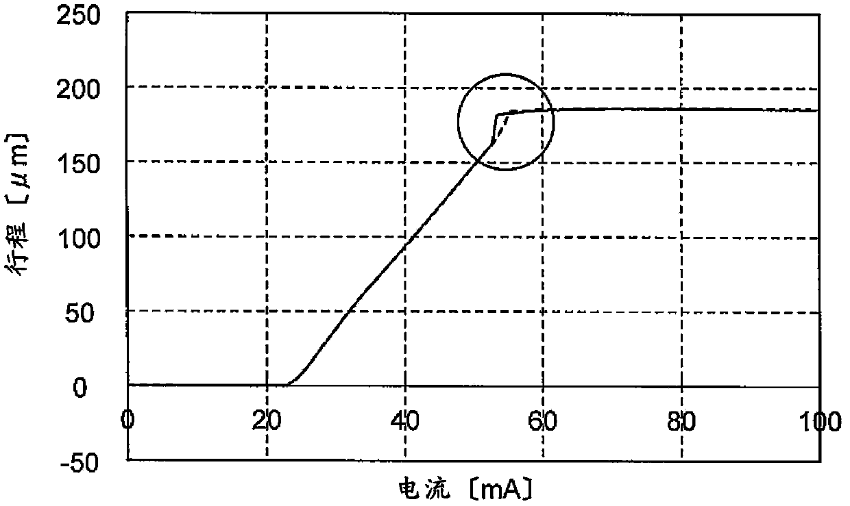
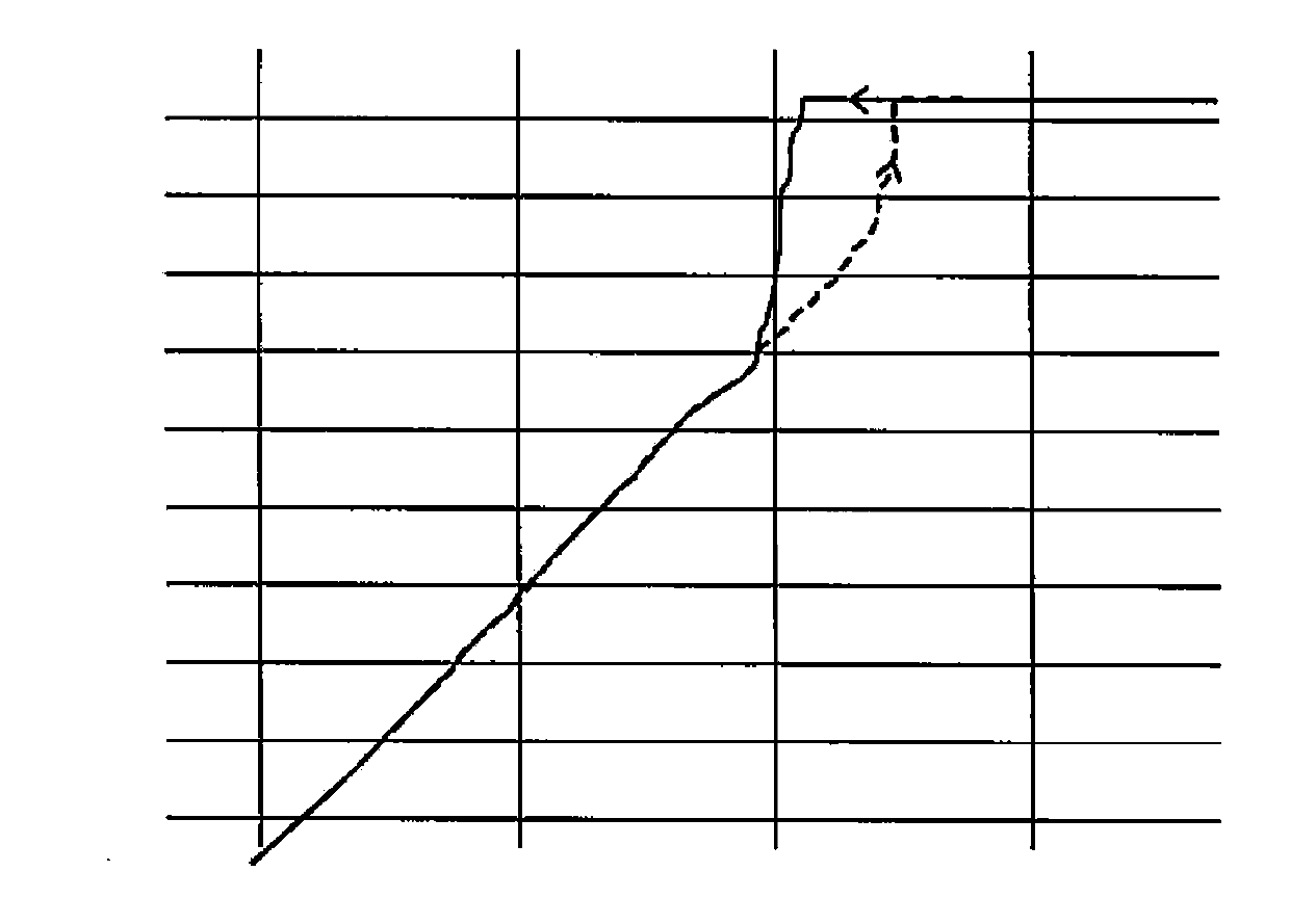
[0102] Figure 12 It is a graph showing the effect of improving the upper side hysteresis (μm) near the maximum stroke. exist Figure 11 In the figure, the left side shows the upper side hysteresis (μm) of the related art (NORMAL), the middle part shows the upper side hysteresis (μm) of the above-mentioned first embodiment (upper crease), and the right side ...


PUM


Abstract

The invention provides a lens holder driving device whch is aimed at ensuring the linearity of driving characteristics in a wide scope. A lens holder driving device includes a lens holder in which a lens assembly is mounted, a driving coil fixed to the lens holder at outside circumference thereof, an outer yoke including an outer hollow cylindrical portion and an ring-shaped end portion disposed an upper end of the outer hollow cylindrical portion, a magnet disposed to an inner wall surface of the outer hollow cylindrical portion so as to be opposite to the driving coil, an elastic member supporting the lens holder in a direction of an optical axis shiftably, and a base disposed at a lower side of the lens holder. The lens holder driving device includes a contact area reduction arrangement (146a) reducing a contact area between the ring-shaped end portion of the outer yoke and an upper end portion of the lens holder.

Description

technical field [0001] The present invention relates to a lens frame driving device, in particular to a lens frame driving device for automatic focusing of a small video camera. Background technique [0002] A small video camera is often mounted on a portable terminal such as a mobile phone with a video camera. This compact video camera uses a lens holder drive unit for autofocus. Conventionally, various autofocus lens holder drive devices have been proposed. [0003] For example, Patent Document 1 (Japanese Unexamined Patent Application Publication No. 2009-251031 ) discloses a lens driving device capable of reducing the number of components and enabling miniaturization. The lens driving device disclosed in this Patent Document 1 includes: a lens holder capable of mounting a lens assembly; a driving coil fixed around the lens holder; a permanent magnet facing the driving coil; and an outer yoke provided with the permanent magnet. ; an elastic member (an upper elastic mem...

Claims


Application Information

Patent Timeline
Patent Type & Authority Applications(China)
IPC IPC(8): G02B7/09G03B13/36H02K33/18
CPCG02B7/08G02B13/001G02B7/09
Inventor 桐井敦
Owner MITSUMI ELECTRIC CO LTD
Why Eureka
Eureka Blog
Learn More