
Grabbing and releasing mechanical arm for automobile electronic rod-shaped components

A technology of automotive electronics and manipulators, which is applied in the direction of manipulators, chucks, manufacturing tools, etc., can solve problems such as prone to defective products, rough movements, and long assembly cycles, so as to improve production efficiency, reduce production costs, and have a high degree of automation. Effect

Inactive Publication Date: 2020-03-27
仙桃市诚宇汽车电器股份有限公司
View PDF1 Cites 0 Cited by
  • Summary
  • Abstract
  • Description
  • Claims
  • Application Information

AI Technical Summary

Problems solved by technology

[0002] In the existing technology, the assembly of some automotive electronic components still relies on manual assembly operations. Manual assembly has human factors, which are prone to defective products, and the assembly cycle is long, low in efficiency and high in cost.
For example, the patent CN106112463A on the rod feeding mechanism of solenoid valve assembly equipment, the patent discloses that the main components of the rod feeding mechanism include a vibrator and a rod tightening device. Rod tightening device, the vibrator also includes a vibrator, a rod vibrating tray, a rod feeding rod, a rod vibrator, a rod vibrator support and a rod distributing unit, but the prior art is still at zero There are problems such as limited precision, low degree of automation, extensive actions, and low efficiency in parts selection, picking, pick-and-place, and positioning.
Although it can replace labor to a certain extent, it still cannot solve the actual assembly problem

Method used


Image

  • Grabbing and releasing mechanical arm for automobile electronic rod-shaped components
  • Grabbing and releasing mechanical arm for automobile electronic rod-shaped components

Examples


Embodiment Construction

[0012] The following will clearly and completely describe the technical solutions in the embodiments of the present invention with reference to the accompanying drawings in the embodiments of the present invention. Obviously, the described embodiments are only some, not all, embodiments of the present invention. Based on the embodiments of the present invention, all other embodiments obtained by persons of ordinary skill in the art without making creative efforts belong to the protection scope of the present invention.

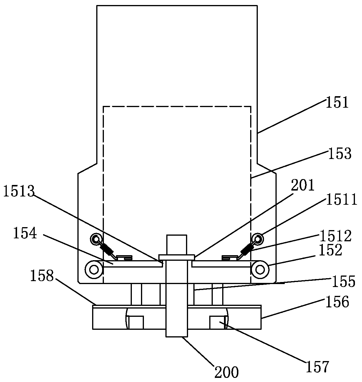
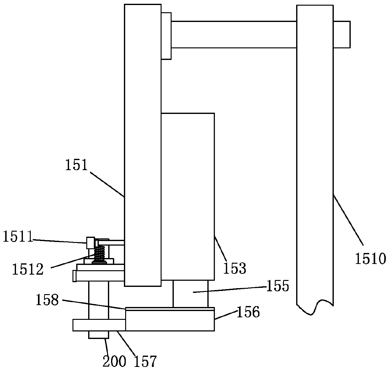
[0013] see Figure 1-2 , in an embodiment of the present invention, a pick-and-place manipulator for automotive electronic rod-shaped components includes a manipulator bracket 151 , a rod-inserting gripper 157 , a pneumatic finger cylinder 156 , and a telescopic cylinder 153 for inserting rods and retrieving materials. Wherein the manipulator support 151 can be fixed on any workbench by the strut 1510 .

[0014] Two movable plates 154 are hinged at the bottom...


PUM


Abstract

The invention discloses a grabbing and releasing mechanical arm for automobile electronic rod-shaped components. The mechanical arm comprises a mechanical arm support, an inserting rod taking clampingjaw, a pneumatic finger air cylinder and an inserting rod taking telescopic air cylinder. The mechanical arm is characterized in that two movable plates are hinged to the bottom of the mechanical armsupport; the two movable plates are oppositely arranged; a reset spring is mounted on one movable plate; a finger cylinder mounting plate is horizontally arranged under the movable plate; the pneumatic finger air cylinder is fixed to the bottom of the finger cylinder mounting plate; the inserting rod taking clamping jaw is arranged at the end of the pneumatic finger air cylinder; the inserting rod taking telescopic air cylinder is arranged on the rear portion of the mechanical arm support in the vertical direction; and an air cylinder push rod of the inserting rod taking telescopic air cylinder is connected with the top of the finger air cylinder mounting plate. The mechanical arm is high in automation degree, can automatically pick up, grab and release the inserting rods and the like, isaccurate in batching, improves the production efficiency and reduces the production cost.

Description

technical field [0001] The invention relates to the field of mechanical automation, in particular to a pick-and-place manipulator for automotive electronic rod-shaped components. Background technique [0002] In the prior art, the assembly of some automotive electronic components still relies on manual assembly operations. Manual assembly has human factors, prone to defective products, and long assembly cycle, low efficiency and high cost. Such as the rod feeding mechanism of the patent CN106112463A solenoid valve assembly equipment, the patent discloses that the main components of the rod feeding mechanism include a vibrator and a rod tightening device. The rod tightening device, the vibrator also includes a vibrator, a rod vibrating tray, a rod feeding rod, a rod vibrator, a rod vibrator bracket and a rod distributing unit, but the prior art is still at zero There are problems such as limited precision, low degree of automation, extensive actions, and low efficiency in pa...

Claims


Application Information

Patent Timeline
IPC IPC(8): B25J15/00
CPCB25J15/00
Inventor 周其林
Owner 仙桃市诚宇汽车电器股份有限公司
Learn More