
A cement prefabricated splicing installation part

A technology of splicing parts and mounting parts, which is applied in the direction of construction and building construction, can solve problems such as inability to splice cement splicing parts, problems, cracks in cement splicing parts, etc., and achieve the effect of avoiding low connection effect

Active Publication Date: 2021-03-09
海南电网有限责任公司
View PDF8 Cites 0 Cited by
  • Summary
  • Abstract
  • Description
  • Claims
  • Application Information

AI Technical Summary

Problems solved by technology

[0002] With the continuous development of the construction industry, it has further promoted the continuous improvement of the manufacturing level of construction products. In the current construction process, most of the cement accessories will be prefabricated, so that the cement accessories will be installed during the construction process. Through the cement accessories The installation can further improve the construction efficiency. In the installation process of the current cement fittings, most of the cement fittings are assembled and the cement is solidified to realize the installation of the two cement fittings. Although the two cement fittings can be installed through the cement Assembling, but after the two cement fittings are assembled, as time goes by, the two cement splicing pieces will further cause cracks, which will cause serious problems to the quality of the cement splicing pieces. At the same time, when the volume of the two cement splicing pieces is relatively large In the case of a large size, due to the large volume of the cement piece, the two cement splicing pieces cannot be spliced ​​through the cement

Method used


Image

  • A cement prefabricated splicing installation part
  • A cement prefabricated splicing installation part
  • A cement prefabricated splicing installation part

Examples


Embodiment Construction

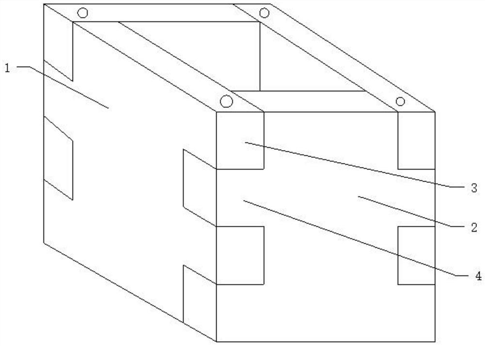
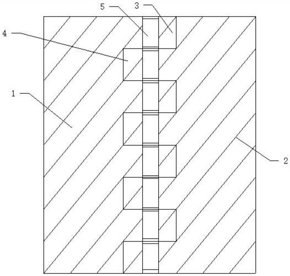
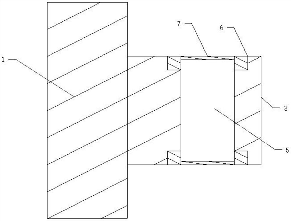
[0026] Such as Figure 1 to 4 Distance Figure 1 to 4 For the first structural schematic, a cement prefabricated mounting member includes a first prefabricating member 1, and a first prefabricating member 1 is provided with a first card block 3, further comprising a second pre-forming splicing member 2, The second prefabricated splicing member 2 is provided with a second card block 4, the first card block 3, and the second card block 1 side corresponding setting, the first card block 3 and the second card block 4 intersect Set, the first engaging block 3 and the second card block 4 are respectively provided with a corresponding first pairing hole 5, and both ends of the first pair of holes 5 are respectively provided with a sealing film 7, which is respectively. The first pair of joint holes 5 is provided with a cement, and the first card block 3 and the second block 4 are coupled, and the first pairing hole 5 corresponds to the connection, and includes one and the first docking. ...


PUM


Abstract

The invention discloses a cement prefabricated splicing installation part, which includes a first prefabricated splicing part, a first clamping block is arranged on the first prefabricated splicing part, and a second prefabricated splicing part, and the second prefabricated splicing part is still arranged There is a second clamping block, the first clamping block and the second clamping block are arranged side by side correspondingly, the first clamping block and the second clamping block are arranged in cross correspondence, the first clamping block and the second clamping block The connecting blocks are respectively provided with corresponding first butt joint holes, the two ends of the first butt joint holes are respectively provided with a sealing film, the first joint holes are provided with cement, and the first clamping block and the second joint After the two clamping blocks are correspondingly clamped, the first butt joint holes are connected correspondingly. After the cement can be poured into the first connection hole, the first prefabricated splicing piece and the second prefabricated joint can be further connected after the cement is solidified. The splicing parts are connected, so as to avoid the problem of poor connection effect caused by the connection of two parts with cement slurry.

Description

Technical field [0001] The present invention relates to a cement prefabricated, and more particularly to a cement prefabricated mounting member, and more particularly to a cement prefabricated mounting member capable of fixing the installation. Background technique [0002] With the continuous development of the construction industry, further promotion of the continuous improvement of building product manufacturing levels, most of the cement accessories in the current construction process, thereby installing cement accessories in the process of construction, through cement accessories The installation can further improve the construction efficiency, where most of the cement accessories are assembled after the installation of cement accessories, the installation of two cement accessories is achieved by cement solidification, although two cement accessories can be carried out through cement Assembly, but after the two cement fittings, the two cement gathers have caused cracks over ...

Claims


Application Information

Patent Timeline
Patent Type & Authority Patents(China)
IPC IPC(8): E04B1/04E04B1/41
CPCE04B1/04E04B1/043E04B1/41E04B1/4107E04B2001/4192
Inventor 周德旺
Owner 海南电网有限责任公司
Learn More