
Vibration isolator

A vibration isolator, the other side of the technology, applied in the direction of friction shock absorber, high internal friction spring, etc., can solve the problem of not being able to meet the requirements of large stiffness of the powertrain, large damping, small stiffness, small damping, and inability to effectively suppress low frequency and large Amplitude vibration, unfavorable impact and other problems, to achieve the effect of improving stiffness, limiting displacement, and benefiting high-frequency vibration reduction

Active Publication Date: 2020-03-27
WEICHAI POWER CO LTD
View PDF8 Cites 6 Cited by
  • Summary
  • Abstract
  • Description
  • Claims
  • Application Information

AI Technical Summary

Problems solved by technology

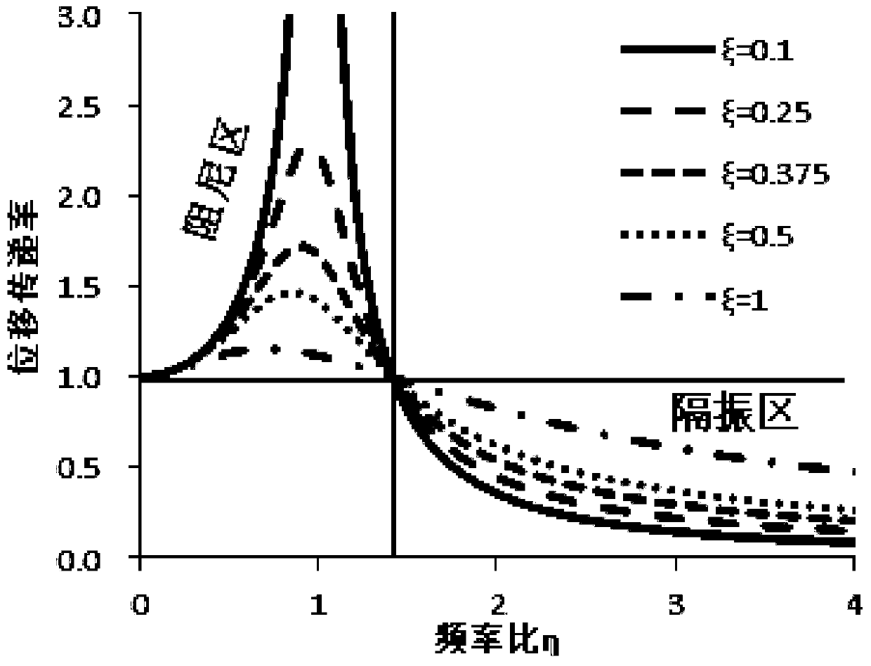
If you choose a mount with smaller stiffness and damping, the smaller the stiffness, the higher the ratio of the excitation frequency to the natural frequency, and the smaller the damping, it is good for vibration isolation and can reduce high-frequency vibration noise. Damping is not conducive to preventing shocks and cannot effectively suppress low-frequency large-amplitude vibrations
[0004] The existing adjustable stiffness suspension structure has only one spring, and the stiffness can be adjusted during the initial installation. Once the installation is completed, the stiffness cannot be changed according to the actual operating conditions, and the stiffness must be adjusted manually. Currently, the damping cannot be adjusted.
Therefore, the rubber mount cannot simultaneously meet the requirements of the powertrain for high stiffness and large damping at low frequencies and low stiffness and small damping at high frequencies.

Method used


Image

  • Vibration isolator
  • Vibration isolator

Examples


Embodiment Construction

[0034] In order to make the technical problems solved by the present invention, the technical solutions adopted and the technical effects achieved clearer, the technical solutions of the embodiments of the present invention will be further described in detail below in conjunction with the accompanying drawings. Obviously, the described embodiments are only the technical solutions of the present invention. Some, but not all, embodiments. Based on the embodiments of the present invention, all other embodiments obtained by those skilled in the art without creative efforts fall within the protection scope of the present invention.

[0035] In the description of the present invention, unless otherwise clearly specified and limited, the terms "connected", "connected" and "fixed" should be understood in a broad sense, for example, it can be a fixed connection, a detachable connection, or an integrated ; It can be a mechanical connection or an electrical connection; it can be a direct...


PUM


Abstract

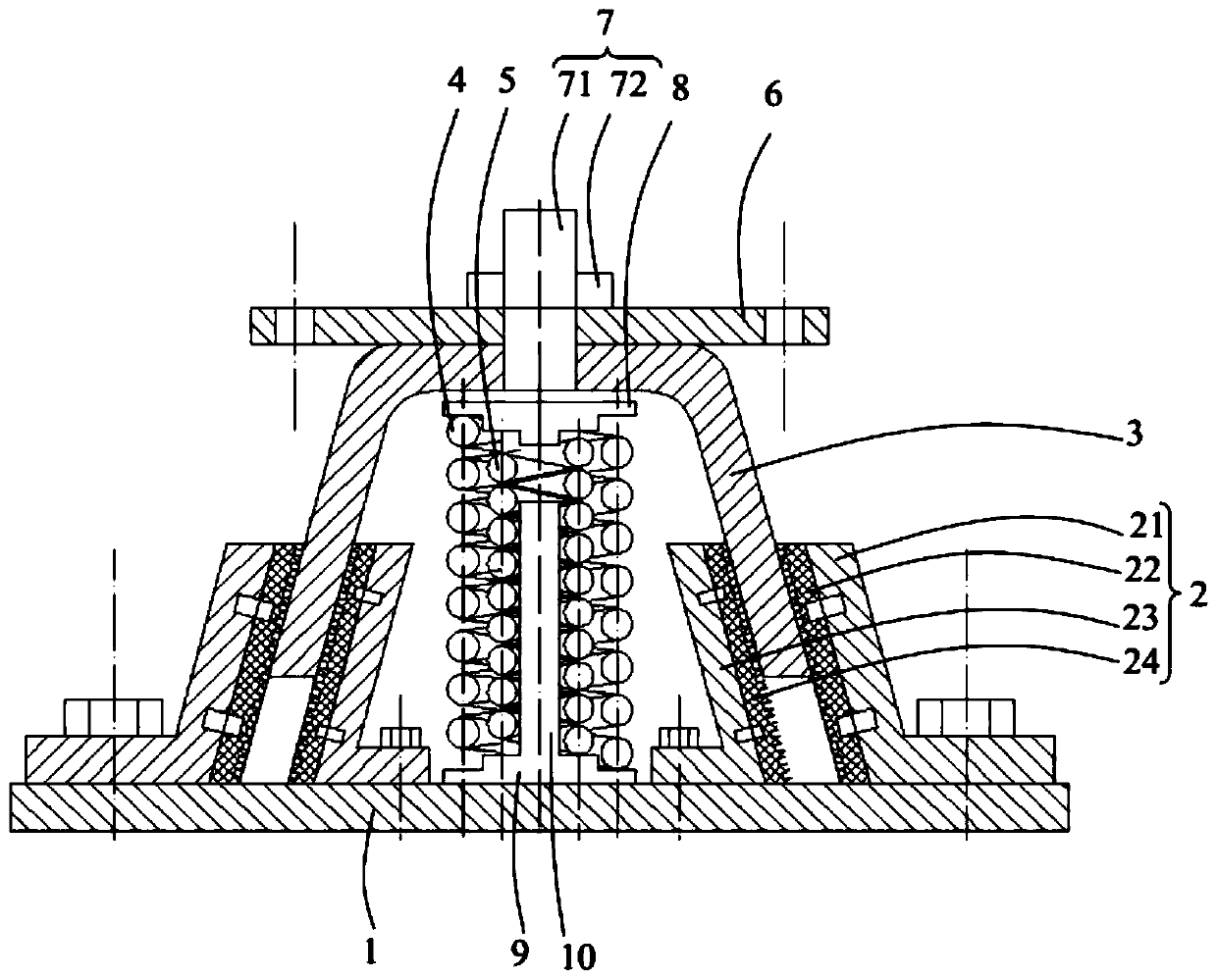
The invention belongs to the technical field of an automobile and discloses a vibration isolator. The vibration isolator comprises a bottom plate, a friction assembly arranged on the bottom plate, a shell, a first reset piece and a second reset piece, wherein the bottom of the shell is arranged in the friction assembly in a sliding mode and can abut against the friction assembly, the first reset piece is arranged in the shell, two ends of the first reset piece abut against an inner wall of the shell and the bottom plate respectively, the second reset piece is arranged in the first reset pieceand connected with the first reset piece in parallel, and two ends of the second reset piece selectively abut against an inner wall of the shell and the bottom plate respectively. The vibration isolator is advantaged in that when high frequency and small load exist, the first reset piece provides rigidity needed by vibration attenuation, the small friction force between the friction assembly and the shell provides damping, rigidity and damping at the moment are small, and high-frequency vibration attenuation is facilitated; when an impact or large-load working condition is met, the two stagesof reset pieces act at the same time, rigidity of the system is improved, the shell can abut against the friction assembly, friction damping is increased, and the requirement for large-rigidity and large-damping isolation impact at low frequency is met.

Description

technical field [0001] The invention relates to the technical field of automobiles, in particular to a vibration isolator. Background technique [0002] At present, the vehicle powertrain mounts are mainly rubber mounts, which are mainly used for high-frequency vibration isolation. According to the characteristics of the rubber structure itself, at the beginning of the design, the stiffness and damping of the rubber material can only be designed with a large value or a small value at the same time. The dynamic stiffness and damping lag angle of the existing rubber isolator vary linearly with the frequency, and the change is very small, which makes it difficult for the dynamic stiffness and damping characteristics of the rubber mount to meet the requirements of broadband isolation and noise reduction under various engine operating conditions. requirements. [0003] In order to prevent the powertrain from generating a large displacement when the car is braking, turning or dr...

Claims


Application Information

Patent Timeline
Patent Type & Authority Applications(China)
IPC IPC(8): F16F3/10F16F7/08
CPCF16F3/10F16F7/08
Inventor 徐止听张中业付春丽
Owner WEICHAI POWER CO LTD
Learn More