Boiler fluidized bed multistage slag cooling system

A fluidized bed and boiler technology, applied in the field of boiler fluidized bed multi-stage slag cooling system, can solve problems such as unfavorable slag removal system and safe operation of equipment, slag stuck, endangering life safety, etc. The effect of avoiding damage to parts and accelerating the cooling rate

Active Publication Date: 2020-03-27
济南黄台煤气炉有限公司
View PDF6 Cites 0 Cited by
  • Summary
  • Abstract
  • Description
  • Claims
  • Application Information

AI Technical Summary

Problems solved by technology

[0002] Fluidized bed refers to suspending a large number of solid particles in the moving fluid, so that the particles have some apparent characteristics of the fluid. The temperature of the slag produced by the fluidized bed boiler is relatively high. If it is directly discharged or enters the slag removal system, It will endanger the safety of people, and it is not conducive to the safe operation of the slag removal system and equipment. Therefore, it needs to be cooled for recycling. The traditional slag cooling method is to put the slag into the existing slag cooler for cooling. At that time, Some problems may be encountered when the existing slag cooler works:
[0003] 1. When the slag cools down in the slag cooler, the slag may be stuck, resulting in blockage and difficult slag discharge. Since the entire slag cooling process is in a sealed environment and is in working condition, it is difficult to clean the blockage in time;
[0004] 2. The existing slag cooler has a large amount of slag cooling at one time. During the slag cooling process, the cooling effect of the inner and outer layers of the slag pile is different, and it needs to consume a long working time to cool the slag. ,low efficiency

Method used


Image

  • Boiler fluidized bed multistage slag cooling system
  • Boiler fluidized bed multistage slag cooling system
  • Boiler fluidized bed multistage slag cooling system

Examples


Embodiment Construction

[0027] Embodiments of the present invention will be described below with reference to the drawings. In the process, in order to ensure the clarity and convenience of illustration, we may exaggerate the width of the lines or the size of the constituent elements in the diagram.

[0028] In addition, the following terms are defined based on the functions in the present invention, and may be different according to the user's or operator's intention or practice. Therefore, these terms are defined based on the entire content of this specification.

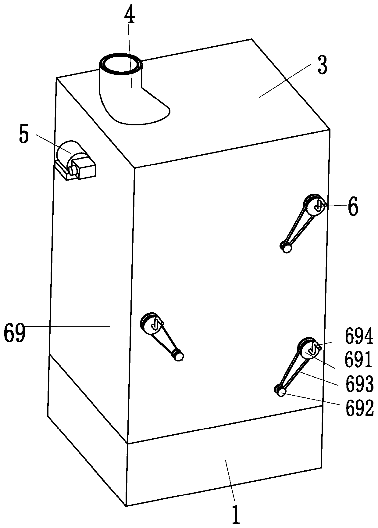
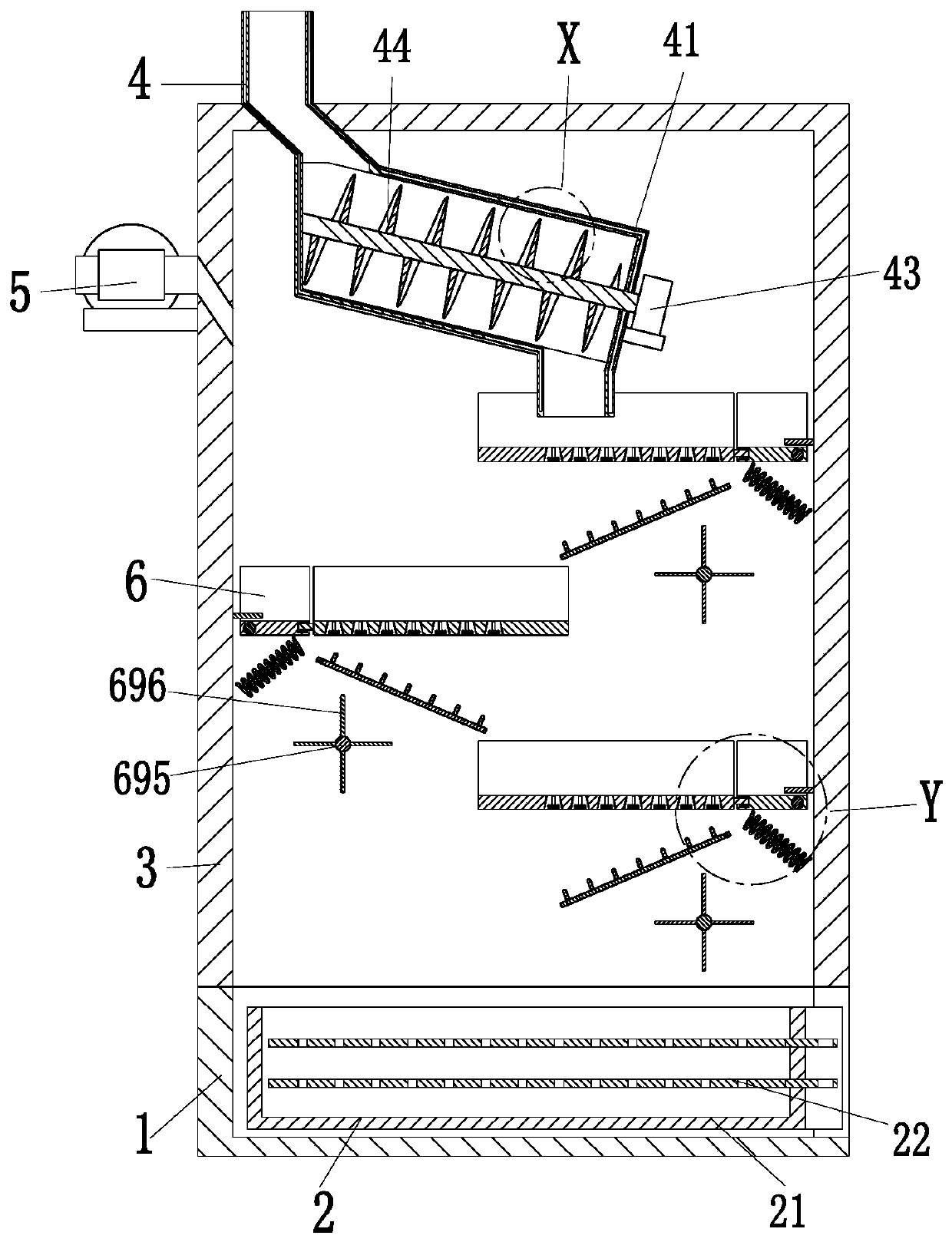
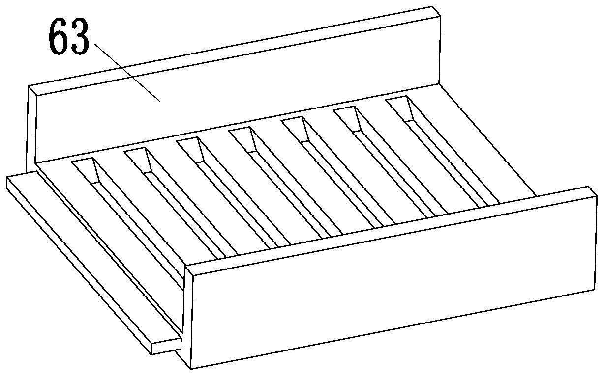
[0029] Such as Figure 1 to Figure 6 As shown, a boiler fluidized bed multi-stage cold slag system includes a base 1, a collection frame 2, a working frame 3, a cooling unit 4, an air pump 5 and a heat dissipation unit 6, and the inside of the base 1 is fitted by sliding Connected with the collection frame 2, the upper end of the base 1 is equipped with a working frame 3, the inner upper end of the working frame 3 is equipped with a co...


PUM


Abstract

The invention relates to a boiler fluidized bed multistage slag cooling system which comprises a base, a collecting frame, a working frame, a cooling unit, an air pump and radiating units, wherein theinterior of the base is in sliding fit with the collecting frame; the working frame is mounted at the upper end of the base; the cooling unit is mounted at the upper end of the interior of the working frame; the radiating units are arranged at the lower end of the interior of the working frame and are arranged in a left-right staggered manner; and the air pump is mounted on the left side wall ofthe working frame. The boiler fluidized bed multistage slag cooling system can solve the following problems: when boiler slag is cooled in a slag cooler, the situation that the boiler slag is jammed to cause blockage and is difficult to discharge may occur; as the entire slag cooling process is carried out in the sealing environment and is in the working state, the blocking position is difficult to clean timely; one-time slag cooling quantity of the existing slag cooler is larger, during the slag cooling process, the cooling effects of the internal and external layers in a boiler slag pile arenot equal, and longer working time needs to be consumed to carry out slag cooling treatment on the internal and external layers in the boiler slag pile.

Description

technical field [0001] The invention relates to the technical field of boiler slag treatment, in particular to a boiler fluidized bed multi-stage cooling slag system. Background technique [0002] Fluidized bed refers to suspending a large number of solid particles in the moving fluid, so that the particles have some apparent characteristics of the fluid. The temperature of the slag produced by the fluidized bed boiler is relatively high. If it is directly discharged or enters the slag removal system, It will endanger the safety of people, and it is not conducive to the safe operation of the slag removal system and equipment. Therefore, it needs to be cooled for recycling. The traditional slag cooling method is to put the slag into the existing slag cooler for cooling. At that time, Some problems may be encountered when the existing slag cooler works: [0003] 1. When the slag cools down in the slag cooler, the slag may be stuck, resulting in blockage and difficult slag dis...

Claims


Application Information

Patent Timeline
IPC IPC(8): F23C10/24
CPCF23C10/24
Inventor 李永成李新发
Owner 济南黄台煤气炉有限公司
Why Eureka
Try Eureka