Cutter damage detection method based on image region division

A damage detection and image area technology, applied in the field of tool detection, can solve problems such as tool damage, achieve good accuracy and improve detection accuracy.

Active Publication Date: 2020-03-27
NANJING UNIV OF SCI & TECH +2
View PDF4 Cites 10 Cited by
  • Summary
  • Abstract
  • Description
  • Claims
  • Application Information

AI Technical Summary

Problems solved by technology

[0004] The purpose of the present invention is to provide a tool damage detection method based on image area division, by simultaneously measuring the wear area and the damaged area as the total damage feature of the tool, the accuracy of tool damage monitoring can be improved, and the problem of high tool damage based on machine vision in the machining process can be solved. fine detection problem

Method used


Image

  • Cutter damage detection method based on image region division
  • Cutter damage detection method based on image region division
  • Cutter damage detection method based on image region division

Examples


Embodiment Construction

[0035] The present invention will be further introduced below in conjunction with the accompanying drawings.

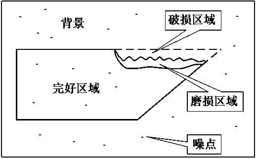
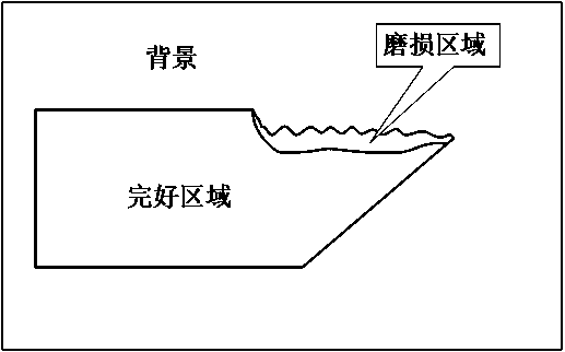
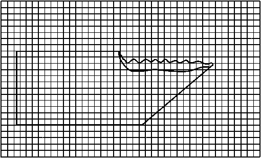
[0036] A tool damage detection method based on image area division is to divide the tool damage area into a worn area and a damaged area, and take the two areas as targets respectively, extract them from the image background and the intact area of ​​the tool, and use the two areas The geometric features of the sum are used as the criterion for determining the degree of tool damage and the type of damage;

[0037] The tool wear area is the wear area formed by the sharp friction between the tool tip and the front and rear surfaces of the tool and the workpiece during the machining process; this area is obtained by scanning and extracting the image pixel based on the gray value of the tool image, after selecting the best threshold;

[0038] The tool damage area is the fine chipping and wear and tear area that occurs on the edge and tip of the tool during tool processing;...


PUM


Abstract

The invention discloses a cutter damage detection method based on image region division. The cutter damage detection method comprises the steps: dividing a cutter damage region into a wear region anda damage region, respectively extracting the two regions, and taking the geometrical characteristics of the sum of the two regions as the discrimination standard of the cutter damage degree and damagetype, wherein the wear region is obtained by equally dividing the image into a plurality of pixel blocks, performing image segmentation on each pixel block to obtain a local threshold value, and performing scanning extraction on the whole image by taking the maximum local threshold value as the optimal threshold value; and the damaged area is obtained by collecting complete cutting edge pixel points in an image, reconstructing the upper and lower boundaries of the cutting edge of the cutter based on data fitting and then extracting through a difference method. The invention provides an effective visual detection method for cutter damage, capable of carrying out high-reliability diagnosis on damage types such as cutter back cutter surface abrasion and cutter tipping.

Description

technical field [0001] The invention belongs to the technical field of tool detection, in particular to a tool damage detection method based on image area division. Background technique [0002] During the cutting process, the tool tip and the front and back of the tool rub against the workpiece violently, and the temperature in the contact area increases sharply. Under the joint erosion of cutting force and cutting heat, the tool is bound to be damaged, which will affect the machining accuracy and cause machine failure in severe cases. Even casualties and huge economic losses. Therefore, it is urgent to develop effective tool damage detection technology. At present, according to the different monitoring methods, tool condition monitoring methods are usually divided into indirect measurement and direct measurement. The indirect detection method is to judge the damage state of the tool by indirectly detecting the signal generated when the tool is worn and damaged. It has st...

Claims


Application Information

Patent Timeline
Patent Type & Authority Applications(China)
IPC IPC(8): G06T7/00G06T7/136G06T7/11G06T7/12G06T7/62
CPCG06T7/0004G06T7/136G06T7/11G06T7/12G06T7/62
Inventor 王禹林叶祖坤查文彬何玉辉汪振华
Owner NANJING UNIV OF SCI & TECH
Why Eureka
Try Eureka