Plugs, sockets and connectors

A socket contact and socket technology, which is applied in the direction of connection, two-part connection device, and parts of the connection device, etc., can solve the problem of increasing the circumferential size of the connector, taking up a large space in the circumferential direction of the socket, and taking up a large space in the circumferential direction of the plug, etc. The problem is to reduce the circumferential size and solve the problem that the circumferential size occupies a large space.

Active Publication Date: 2021-03-23
CHINA AVIATION OPTICAL-ELECTRICAL TECH CO LTD
View PDF8 Cites 0 Cited by
  • Summary
  • Abstract
  • Description
  • Claims
  • Application Information

AI Technical Summary

Problems solved by technology

[0005] The purpose of the present invention is to provide a plug, which is used to solve the problem of the current plug that a shielding ring is provided outside the pins that need shielding to increase the circumferential size of the connector, resulting in a large space occupied by the circumferential direction of the plug; in addition, the purpose of the present invention It is also to provide a socket adapted to the plug, which is used to solve the problem of the large circumferential space of the socket caused by the large axial dimension of the current socket; in addition, the purpose of the present invention is to provide a socket using the above-mentioned plug and socket. Connector

Method used


Image

  • Plugs, sockets and connectors
  • Plugs, sockets and connectors

Examples


Embodiment Construction

[0039] In order to make the object, technical solution and advantages of the present invention clearer, the present invention will be further described in detail below in conjunction with the accompanying drawings and embodiments. It should be understood that the specific embodiments described here are only used to explain the present invention, and are not intended to limit the present invention, that is, the described embodiments are only some of the embodiments of the present invention, but not all of the embodiments. The components of the embodiments of the invention generally described and illustrated in the figures herein may be arranged and designed in a variety of different configurations.

[0040] Accordingly, the following detailed description of the embodiments of the invention provided in the accompanying drawings is not intended to limit the scope of the claimed invention, but merely represents selected embodiments of the invention. Based on the embodiments of the...


PUM


Abstract

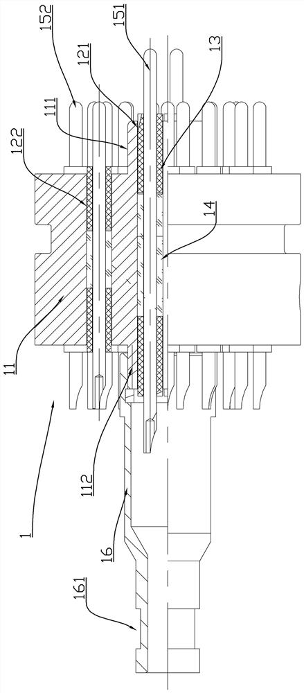
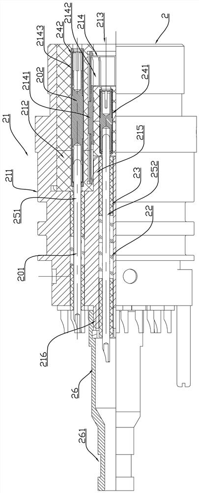
The invention relates to the field of connectors, in particular to a plug, a socket and a connector. The plug comprises a plug conductive shell and a plug contact piece, and the front end of the plugconductive shell is provided with a plug front boss protruding forwards. At least one plug contact piece hole is a first plug hole extending to the plug front boss, the plug contact piece hole locatedbeside the plug front boss is a second plug hole, and the plug front boss arranged on the plug conductive shell is used for being in conductive insertion connection with the hole wall of a shieldingblind hole in a socket matched with a plug so as to shield the first plug hole contact piece. According to the plug provided by the invention, the plug front boss is matched with the shielding blind hole of the socket to shield the first plug hole contact piece, and only one plugging matching surface is arranged between the first plug hole contact piece and the second plug hole contact piece, so that the circumferential size of the plug is reduced, and the technical problem that the existing plug occupies a large space in the circumferential direction is solved.

Description

technical field [0001] The invention relates to the field of connectors, in particular to plugs, sockets and connectors. Background technique [0002] In the petroleum field, electrical connectors used downhole need to withstand high voltage, so they can be called pressure-bearing connectors. When pressure-bearing connectors are used downhole, there are high-voltage cables and various signal lines around them, and the electromagnetic interference is strong. In order to reduce the number of downhole connectors, it is usually necessary to install contacts with different shielding requirements into one connector. The current pressure-bearing connectors generally ensure the electromagnetic shielding of the connector through the conduction between the connected cable shield and the metal shell of the connector. performance. However, the anti-interference energy supply to the electrical signal of the contacts cannot be guaranteed inside the connector. [0003] The Chinese patent...

Claims


Application Information

Patent Timeline
Patent Type & Authority Patents(China)
IPC IPC(8): H01R13/6581H01R13/6585H01R13/6588H01R13/6592H01R13/6461H01R24/00
CPCH01R13/6461H01R13/6581H01R13/6585H01R13/6588H01R13/6592H01R24/00
Inventor 林倩熊贤翠李严亮胡国闯崔艳磊李亮王世光王超王亚楠
Owner CHINA AVIATION OPTICAL-ELECTRICAL TECH CO LTD
Why Eureka
Try Eureka