Wire stripping and cutting machine

A technology of cutting machine and cutting mechanism, which is applied to equipment, cable installation devices, electrical components, etc. for cutting/disconnecting cables. It can solve the problems of difficulty in cable management, knotting and winding, etc., to simplify the structure and facilitate cable management. , The effect of reducing the difficulty of equipment maintenance

Pending Publication Date: 2020-03-27
TAIZHOU SENDUO ENVIRONMENTAL PROTECTION EQUIP TECH CO LTD
View PDF1 Cites 2 Cited by
  • Summary
  • Abstract
  • Description
  • Claims
  • Application Information

AI Technical Summary

Problems solved by technology

[0004] As for the above-mentioned wire stripping machine, the cable is placed between the upper and lower rotating shafts during use, and then the upper and lower rotating shafts will bring the cable between the two blades during the opposite rotation, and then the cable will be The outer insulation sleeve is cut, but in the process of using this wire stripping machine, it is found that as the hobbing progresses, the length of the cut cable becomes longer and longer, and because the blade cuts the cable axially, then One cable will become at least three. As the cutting continues, the length of the cable becomes larger and larger, and it is easy to get knotted and entangled when it is dragged on the ground. After cutting the cable, the insulation may still stick to the metal core. Therefore, it is necessary to manually extract the metal from the insulation for classification and recycling. After the metal core and the insulation are entangled and knotted, it will make it difficult for the staff to manage the wires.

Method used


Image

  • Wire stripping and cutting machine
  • Wire stripping and cutting machine
  • Wire stripping and cutting machine

Examples


Embodiment Construction

[0032] The present invention will be described in further detail below in conjunction with the accompanying drawings.

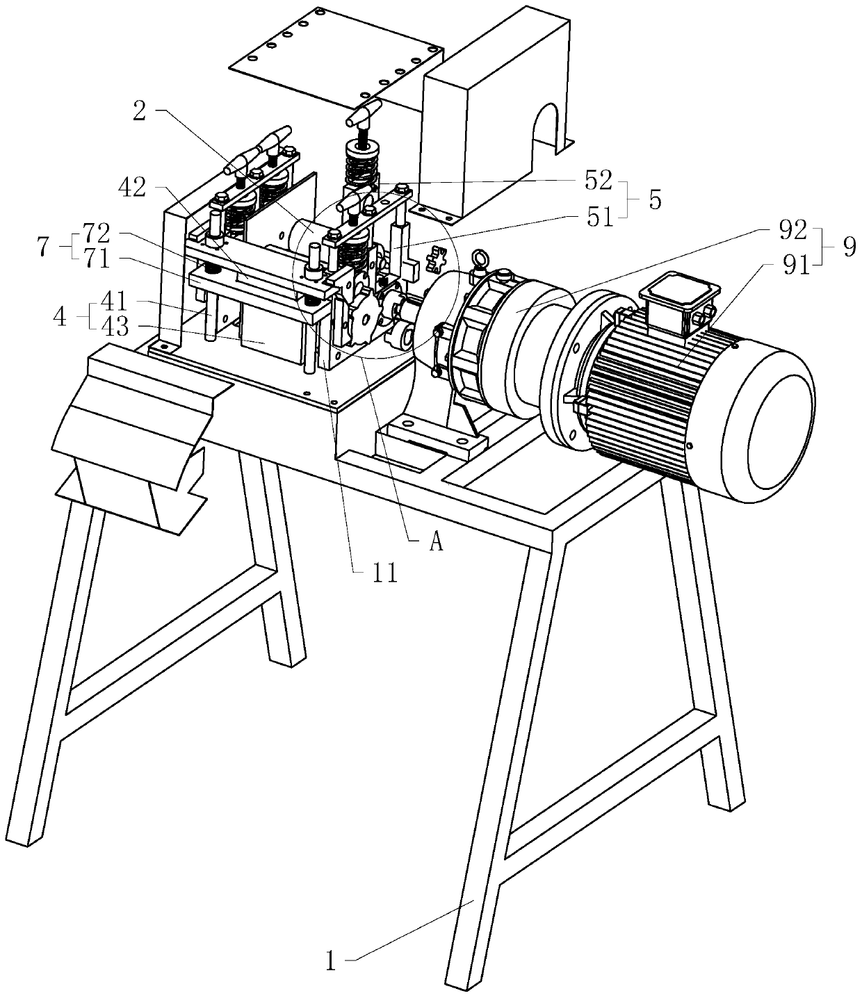
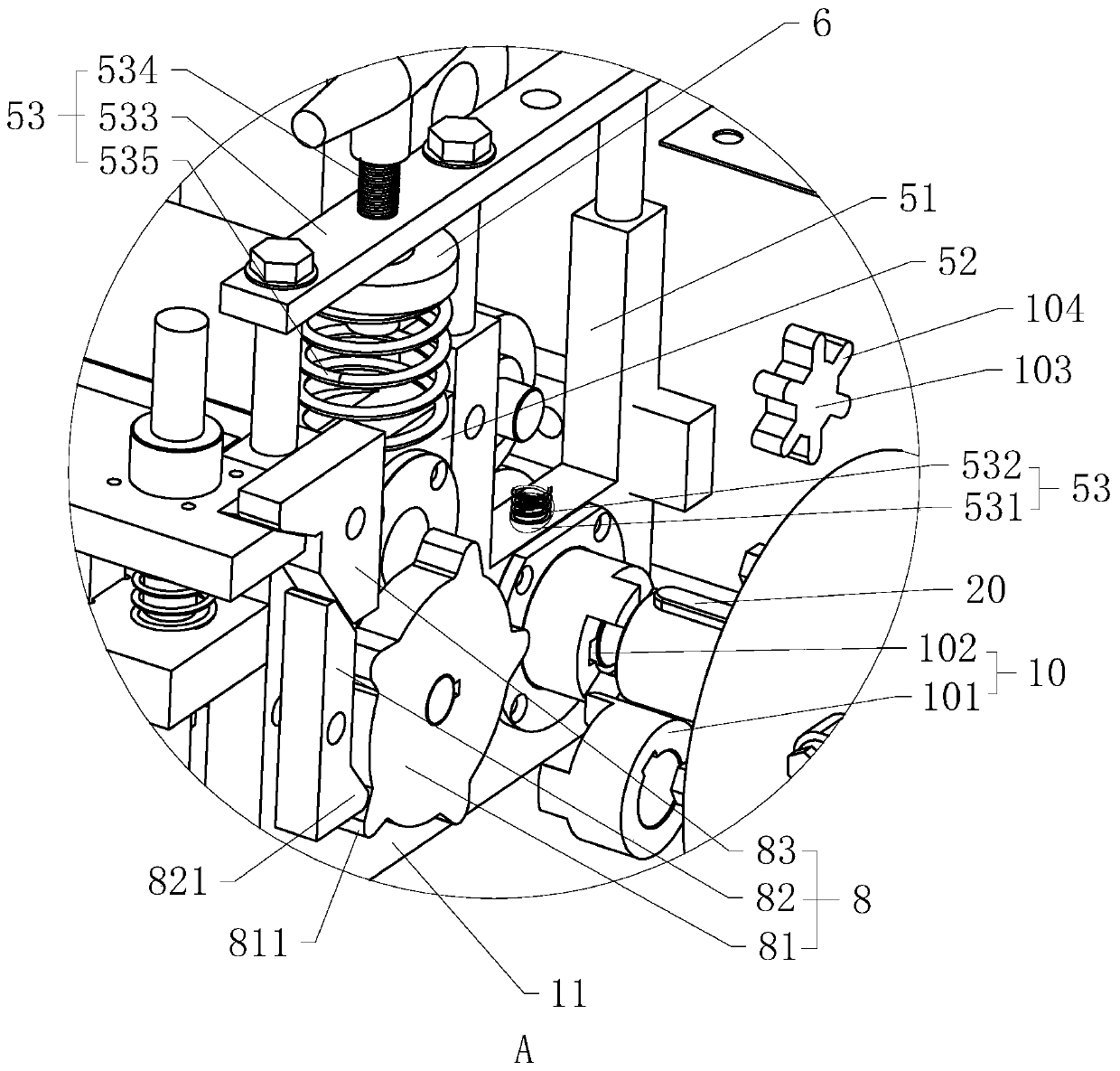
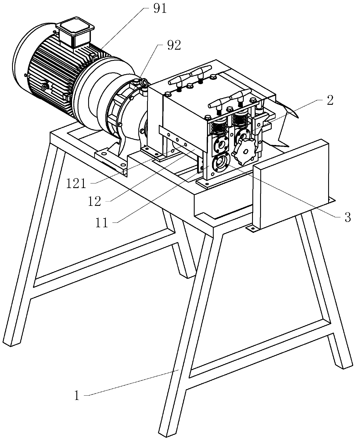
[0033] Such as figure 1 As shown, a wire stripping and cutting machine includes a frame 1, an upper nip roller 2, a lower nip roller 3, a cutting mechanism 4, a linkage mechanism 8, and a driving mechanism 9, and the working surface of the frame 1 is detachably installed with bolts. Two side plates 11 are installed on one side of the frame 1 with an incoming board 12 through bolts, and the two ends of the incoming board 12 are respectively fixed with the two side boards 11; 121, the cable inlet 121 is arranged from left to right in the process of increasing in diameter; the upper nip roller 2 and the lower nip roller 3 work in pairs, and this case is provided with at least two sets of upper and lower nip rollers 3, each of the lower nip rollers The pinch rollers 3 are mutually driven in the form of sprockets and chain belts. Multiple sets of upper and lower ...


PUM


Abstract

The invention discloses a wire stripping and cutting machine and relates to wire stripping equipment which is used for solving the problem that a common wire stripper easily winds and knots a cable. The machine comprises a rack, an upper clamping roller and a lower clamping roller which are installed on the rack in a rotating mode, a cable pressing opening used for extruding a cable is formed between the upper clamping roller and the lower clamping roller, and a driving mechanism which is arranged on the rack and drives the upper clamping roller or the lower clamping roller to rotate. The device further comprises a cut-off mechanism, the cutting-off mechanism comprises a guide column fixed to the rack and located on one side of the wire outlet end of the wire pressing opening, an upper cutting plate arranged on the guide column in a lifting mode and a lower cutting plate installed on the rack and used in cooperation with the upper cutting plate, the upper cutting plate and the lower clamping roller are in linkage through a linkage mechanism, and then the upper cutting plate is driven to do up-down reciprocating motion. The machine has the following advantages and effects that the cutting mechanism can cut a fractured cable into small sections, so that the cable is not prone to being wound and knotted due to the fact that the cable is dragged too long, people can conveniently pull a metal core out of an insulating sheath, and therefore the purpose of conveniently arranging the cable is achieved.

Description

technical field [0001] The invention relates to wire stripping equipment, in particular to a wire stripping and cutting machine. Background technique [0002] Social civilization has gone through the age of steam, the age of internal combustion engines, and the age of electricity, and now it has entered the age of information. As time goes by, technology is always improving. In the context of the information age, all information can be transmitted quickly through electrical signals, and the transmission of electrical signals requires the use of specific media—cables as carriers. After these cables are used up, their materials can be transmitted. For recycling, the old metal in the cable is generally re-melted and cast into other products as needed. [0003] At present, the utility model patent with the authorized notification number CN204407105U discloses a multifunctional wire stripping machine, including a support arranged on the frame, an upper rotating shaft and a lower...

Claims


Application Information

Patent Timeline
Patent Type & Authority Applications(China)
IPC IPC(8): H02G1/00H02G1/12
CPCH02G1/005H02G1/12
Inventor 缪继球
Owner TAIZHOU SENDUO ENVIRONMENTAL PROTECTION EQUIP TECH CO LTD
Why Eureka
Try Eureka