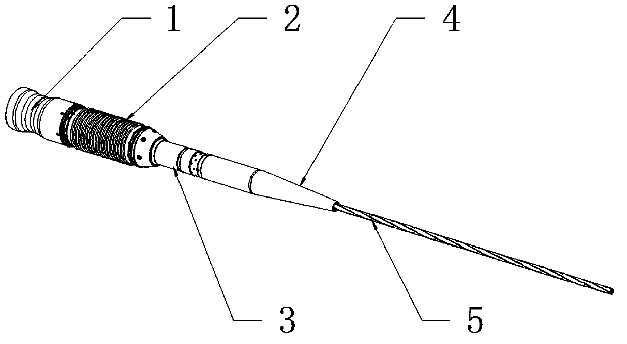
Submarine photoelectric separation equipment
A technology of photoelectric separation and equipment, which is applied in the field of submarine observation equipment and submarine observation network, can solve the problem that the reliability cannot meet the long-term work, etc., and achieve the effect of reliable sealing performance, improved sealing reliability, and high sealing reliability
- Summary
- Abstract
- Description
- Claims
- Application Information
AI Technical Summary
Problems solved by technology
Method used
Image
Examples
Embodiment 1
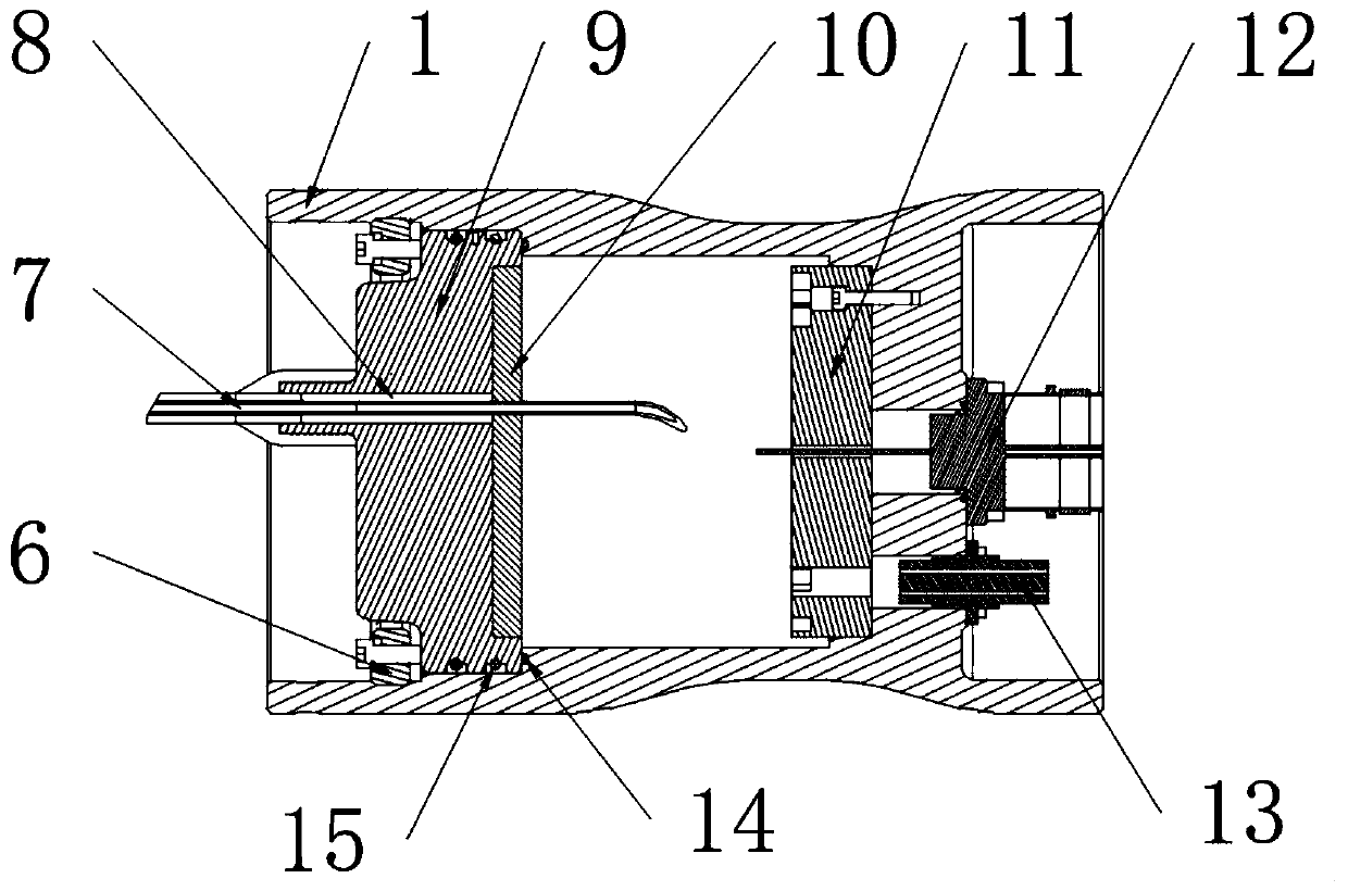
[0031] see figure 2 As shown, the embodiment of the present invention provides a kind of subsea photoelectric separation equipment, comprising:
[0032] Anti-pressure cylinder 1, the first end of the anti-pressure cylinder 1 is an open end, and the second end away from the first end is a closed end. The anti-pressure cylinder 1 is a hollow structure similar to a cup, and its shape is preferably a cylinder structure, the anti-pressure cylinder 1 adopts an open end and a closed end structure, which can significantly reduce the sealing leakage point. Compared with the open structure at both ends in the prior art, the sealing performance is higher and the sealing reliability is higher.
[0033] End cap 9, the end cap 9 is located in the pressure-resistant cylinder 1, and the end cap 9 and the pressure-resistant cylinder 1 jointly form a sealed cavity structure, and a through hole for penetrating the photoelectric composite cable 7 is opened on the end cap 9. After the tail end ...
Embodiment 2
[0039] see figure 2 As shown, the embodiment of the present invention provides a seabed photoelectric separation device. The difference between this embodiment and Embodiment 1 is that an annular flange sealingly connected with the end cover 9 is provided on the inner wall of the pressure-resistant cylinder 1, and the annular flange is The edge is used to limit the end cover 9. On the end cover 9, a metal seal ring 14 is arranged between the end face in the cavity and the connecting surface of the annular flange. The metal seal ring 14 is a metal C-shaped seal ring, and an annular coil spring is sleeved in the metal C-shaped seal ring. 16. Between the outer circle of the end cover 9 and the inner wall of the pressure-resistant cylinder 1, a plurality of O-rings 15 are arranged at intervals. When the end cover 9 is connected to the annular flange, the junction between the end cover 9 and the inner wall of the pressure-resistant cylinder 1 and the annular flange is sealed and...
Embodiment 3
[0041] see figure 2 As shown, the embodiment of the present invention provides a submarine optoelectronic separation device. The difference between this embodiment and Embodiment 1 is that an end cover compression ring 6 is provided on the end cover 9 outside the cavity. The tight ring 6 is provided with a plurality of screw holes along the circumferential direction of the end cover pressing ring 6 . The outer circle of the end cover compression ring 6 is provided with an external thread, and the inner wall of the compression cylinder 1 is provided with an internal thread connected with the end cover compression ring 6, and the end cover compression ring 6 is threadedly connected with the inner wall of the compression cylinder 1 , Screws are penetrated into the threaded holes of the end cover compression ring 6 to resist the end cover 9, so as to realize the compression and sealing between the end cover 9 and the annular flange. When realizing the sealed connection between t...
PUM
 Abstract
Description
Claims
Application Information
 - R&D
- Intellectual Property
- Life Sciences
- Materials
- Tech Scout
- Unparalleled Data Quality
- Higher Quality Content
- 60% Fewer Hallucinations
Browse by: Latest US Patents, China's latest patents, Technical Efficacy Thesaurus, Application Domain, Technology Topic, Popular Technical Reports.
© 2025 PatSnap. All rights reserved.Legal|Privacy policy|Modern Slavery Act Transparency Statement|Sitemap|About US| Contact US: help@patsnap.com


