A kind of subsea photoelectric separation equipment

A technology for optoelectronic separation and equipment, applied in optics, light guides, cable accessories, etc., can solve the problem that reliability cannot meet long-term work, etc., and achieve the effect of reliable sealing performance, low overall cost, and high sealing reliability.

Active Publication Date: 2021-10-19
FIBERHOME MARINE NETWORK EQUIP CO LTD +1
View PDF15 Cites 0 Cited by
  • Summary
  • Abstract
  • Description
  • Claims
  • Application Information

AI Technical Summary

Problems solved by technology

[0005] The object of the present invention is to provide a seabed photoelectric separation device in order to overcome the shortage that the reliability of the sealing of the existing photoelectric separation device in the above background technology cannot meet the requirements of long-term work in deep water conditions

Method used


Image

  • A kind of subsea photoelectric separation equipment
  • A kind of subsea photoelectric separation equipment
  • A kind of subsea photoelectric separation equipment

Examples


Embodiment 1

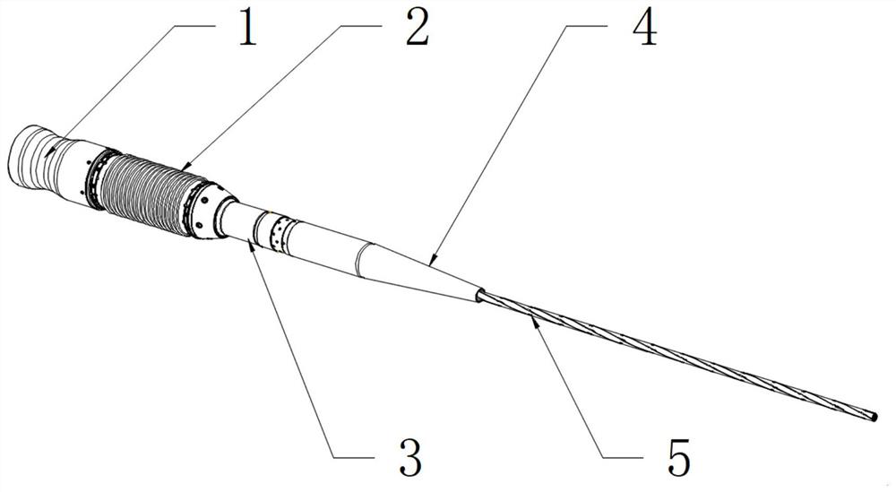
[0031] see figure 2 As shown, the embodiment of the present invention provides a kind of subsea photoelectric separation equipment, comprising:

[0032] Anti-pressure cylinder 1, the first end of the anti-pressure cylinder 1 is an open end, and the second end away from the first end is a closed end. The anti-pressure cylinder 1 is a hollow structure similar to a cup, and its shape is preferably a cylinder structure, the anti-pressure cylinder 1 adopts an open end and a closed end structure, which can significantly reduce the sealing leakage point. Compared with the open structure at both ends in the prior art, the sealing performance is higher and the sealing reliability is higher.

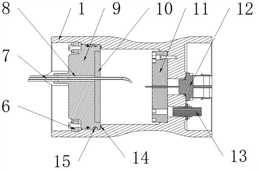
[0033] End cap 9, the end cap 9 is located in the pressure-resistant cylinder 1, the end cap 9 and the pressure-resistant cylinder 1 jointly form a sealed cavity structure, and a through hole for penetrating the photoelectric composite cable 7 is opened on the end cap 9, the photoelectric compos...

Embodiment 2

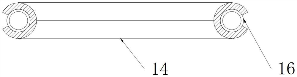
[0039] see figure 2 As shown, the embodiment of the present invention provides a seabed photoelectric separation device. The difference between this embodiment and Embodiment 1 is that an annular flange sealingly connected with the end cover 9 is provided on the inner wall of the pressure-resistant cylinder 1, and the annular flange is The edge is used to limit the end cover 9. On the end cover 9, a metal seal ring 14 is arranged between the end face in the cavity and the connecting surface of the annular flange. The metal seal ring 14 is a metal C-shaped seal ring, and an annular coil spring is sleeved in the metal C-shaped seal ring. 16. Between the outer circle of the end cover 9 and the inner wall of the pressure-resistant cylinder 1, a plurality of O-rings 15 are arranged at intervals. When the end cover 9 is connected to the annular flange, the junction between the end cover 9 and the inner wall of the pressure-resistant cylinder 1 and the annular flange is sealed and...

Embodiment 3

[0041] see figure 2 As shown, the embodiment of the present invention provides a submarine optoelectronic separation device. The difference between this embodiment and Embodiment 1 is that an end cover compression ring 6 is provided on the end cover 9 outside the cavity. The tight ring 6 is provided with a plurality of screw holes along the circumferential direction of the end cover pressing ring 6 . The outer circle of the end cover compression ring 6 is provided with an external thread, and the inner wall of the compression cylinder 1 is provided with an internal thread connected with the end cover compression ring 6, and the end cover compression ring 6 is threadedly connected with the inner wall of the compression cylinder 1 , Screws are penetrated into the threaded holes of the end cover compression ring 6 to resist the end cover 9, so as to realize the compression and sealing between the end cover 9 and the annular flange. When realizing the sealed connection between t...


PUM


Abstract

The invention discloses a seabed photoelectric separation device, which belongs to the technical field of seabed observation equipment and seabed observation network. End; end cover, the end cover is located in the pressure-resistant cylinder, and together with the pressure-resistant cylinder to form a sealed cavity structure, the end cover is provided with a through hole for passing through the photoelectric composite cable; the injection molding body, the injection molding body is located in the end cover In the through hole, the photoelectric composite cable and the end cover are sealed and connected by an injection molding body; the cable watertight connector and the optical fiber watertight connector are respectively sealed and connected to the second end. The anti-pressure cylinder of the present invention adopts the first end as an open end, and the second end far away from the first end is a closed end, wherein the open end is sealed and connected with an end cover, and the sealing between the end cover of the device and the tail end of the photoelectric composite cable It is sealed by injection molding, and its sealing performance is more reliable than that of sealing rings and other sealing methods, and it is suitable for deep-water 4KM marine environments.

Description

technical field [0001] The invention relates to the technical field of seabed observation equipment and seabed observation network, in particular to a seabed photoelectric separation device. Background technique [0002] The submarine observation network can be applied to the development of submarine resources, submarine environment monitoring, marine scientific research, marine military network construction and other fields. Since ordinary submarine cables alone cannot achieve long-distance and large-capacity information transmission, submarine communication with photoelectric composite cables must be used. system. [0003] The submarine observation network is an ocean observation network formed by connecting shore-based equipment, photoelectric composite cables, and submarine main base stations. The main subsea base station is an important device to realize power conversion, data aggregation, transmission and control. The backbone cable of the submarine observation netwo...

Claims


Application Information

Patent Timeline
Patent Type & Authority Patents(China)
IPC IPC(8): H02G15/00G02B6/44
CPCG02B6/4446H02G15/00
Inventor 谢路宦益国孙健
Owner FIBERHOME MARINE NETWORK EQUIP CO LTD
Why Eureka
Try Eureka