A method for replacing protective devices without power failure

A protection device and backup protection technology, applied in emergency protection circuit devices, circuit devices, emergency protection devices with automatic disconnection, etc., can solve problems affecting user experience, production, life inconvenience, etc., and improve user experience and safety. Guaranteed, operability effect

Active Publication Date: 2022-03-01
国网河北省电力有限公司邯郸市肥乡区供电分公司 +2
View PDF0 Cites 0 Cited by
  • Summary
  • Abstract
  • Description
  • Claims
  • Application Information

AI Technical Summary

Problems solved by technology

It can be seen that this method of replacing the protective device in a power failure brings inconvenience to production and life, and affects the experience of the majority of users.

Method used


Image

  • A method for replacing protective devices without power failure
  • A method for replacing protective devices without power failure
  • A method for replacing protective devices without power failure

Examples


Embodiment 1

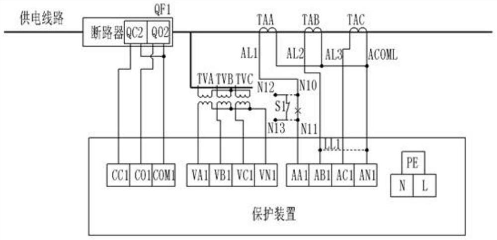
[0029] The terminal and wiring diagram of the protection device are as follows: figure 1 As shown, CC1, CO1, and COM1 are used as control output terminals. The specific meanings are the closing control output terminal, opening control output terminal and control output common terminal, which are connected to the closing coil input terminal of the circuit breaker connected to the power supply line in series, The opening coil input terminal and the common input terminal of the opening and closing coil are connected; VA1, VB1, VC1, and VN1 are used as voltage input terminals, and the specific meanings are A, B, C phase voltage input terminals and voltage input common terminals, which are respectively connected to A, B, C phase voltage input terminals and voltage input common terminals. B and C phase sequence protection voltage transformers are connected to the output terminals of each phase and the common terminal; the protection voltage transformers (TVA, TVB, TVC) are connected ...

Embodiment 2

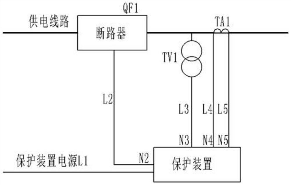
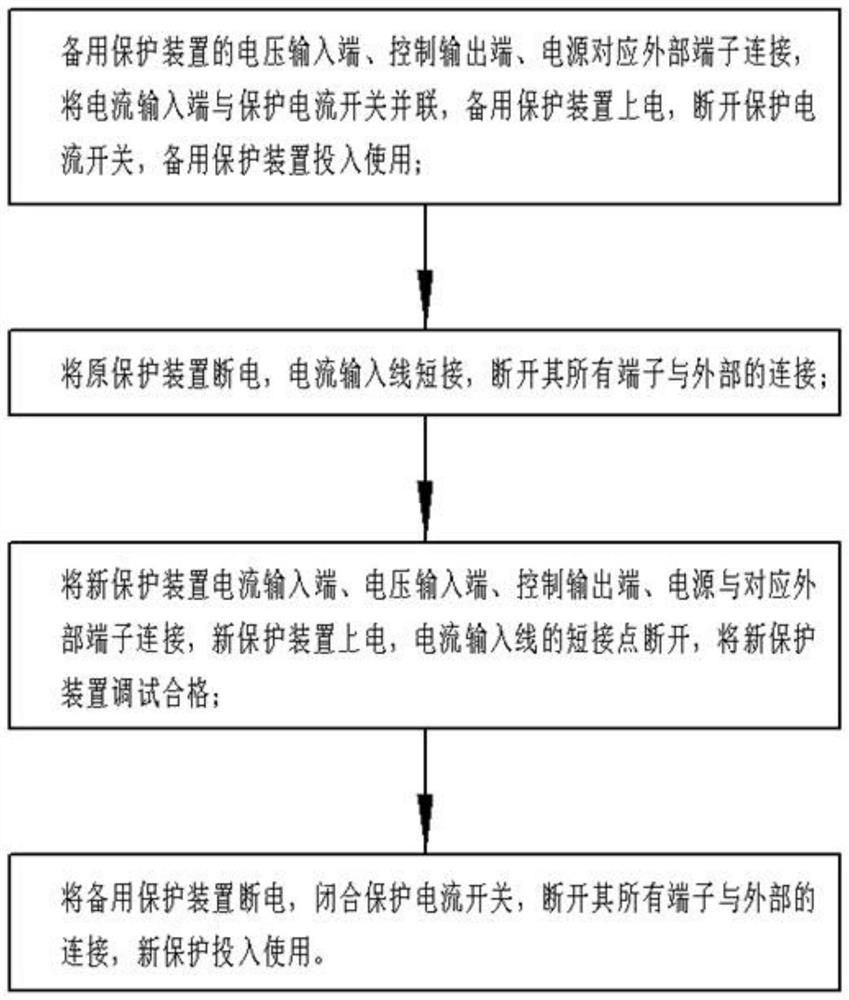
[0038] The replacement steps are as follows Figure 5 As shown, this embodiment is a further improvement of the first embodiment, the difference is that: the backup protection device is first confirmed qualified, and the internal parameters are set in advance. For backup protective devices with external current transformers, the Image 6 The protection current input temporary line L5 in the circuit passes through the iron core of the external current transformer TA2, and its two ends are respectively connected to the terminals N12 and N13 of the protection switch S1, and the output terminal of the external current transformer TA2 is used as the protection current signal The output terminals of the relay are connected to the current input terminals N8 and N9 of the standby protection device through the output lines L3 and L4.

[0039] Before connecting the output terminal of the backup protection device, confirm the opening and closing of the circuit breaker and the coil of th...


PUM


Abstract

The present invention adopts a method for replacing the protection device without power failure. In this method, the backup protection device is connected to the power supply line through the protection current switch connected in series with the output terminal of the protection current transformer, and the original protection device is moved to the power supply line under its protection. In addition, the new device is installed, debugged and put into use, thus solving the problem that the protection device cannot be replaced with power on. The method adds a protection current switch connected in series to the output end of the protection current transformer to the transformation of the original line. The transformation is simple, the technology is mature, the material cost is low, and the versatility is good; the replacement steps are few, the operation is simple, and the operability is strong. Guarantee the continuous power supply of the power system, win more economic benefits for the power supply company and customers, and improve the user experience.

Description

technical field [0001] The invention belongs to the technical field of electric power maintenance, and in particular relates to a replacement method for a substation protection device. Background technique [0002] As a safety component used to monitor abnormalities and faults of the power system and respond in time, the protection device is particularly important for the safe and economical operation of the power system. As a part of the power system, the voltage input terminal and current input terminal are connected to the output terminal of the protection voltage and the output terminal of the protection current in turn; the control output terminal sends a control signal to the circuit breaker connected in series to the power supply line according to the internal logic judgment. To control its opening and closing actions, the protection device is powered by an external power supply such as AC220V. The circuit breaker is connected in series with the power supply line, wh...

Claims


Application Information

Patent Timeline
Patent Type & Authority Patents(China)
IPC IPC(8): H02H3/05H02H3/02
CPCH02H3/05H02H3/02
Inventor 贾支革侯毅君张鹏娥郭家广霍伟伟
Owner 国网河北省电力有限公司邯郸市肥乡区供电分公司
Why Eureka
Try Eureka