Closestool cover plate disassembling and assembling mechanism

A technology for disassembling and assembling mechanism and toilet cover, which is applied to the seat or cover of toilet, household appliances, sanitary equipment, etc., can solve the problems of easy loosening, poor firmness, limited impact force, etc.

Pending Publication Date: 2020-03-31
OCEANWELL XIAMEN IND CO LTD
View PDF0 Cites 0 Cited by
  • Summary
  • Abstract
  • Description
  • Claims
  • Application Information

AI Technical Summary

Problems solved by technology

However, the current installation method of the toilet cover is not firm enough, the impact force it can withstand is limited, and it is easy to loosen

Method used


Image

  • Closestool cover plate disassembling and assembling mechanism
  • Closestool cover plate disassembling and assembling mechanism
  • Closestool cover plate disassembling and assembling mechanism

Examples


Embodiment 1

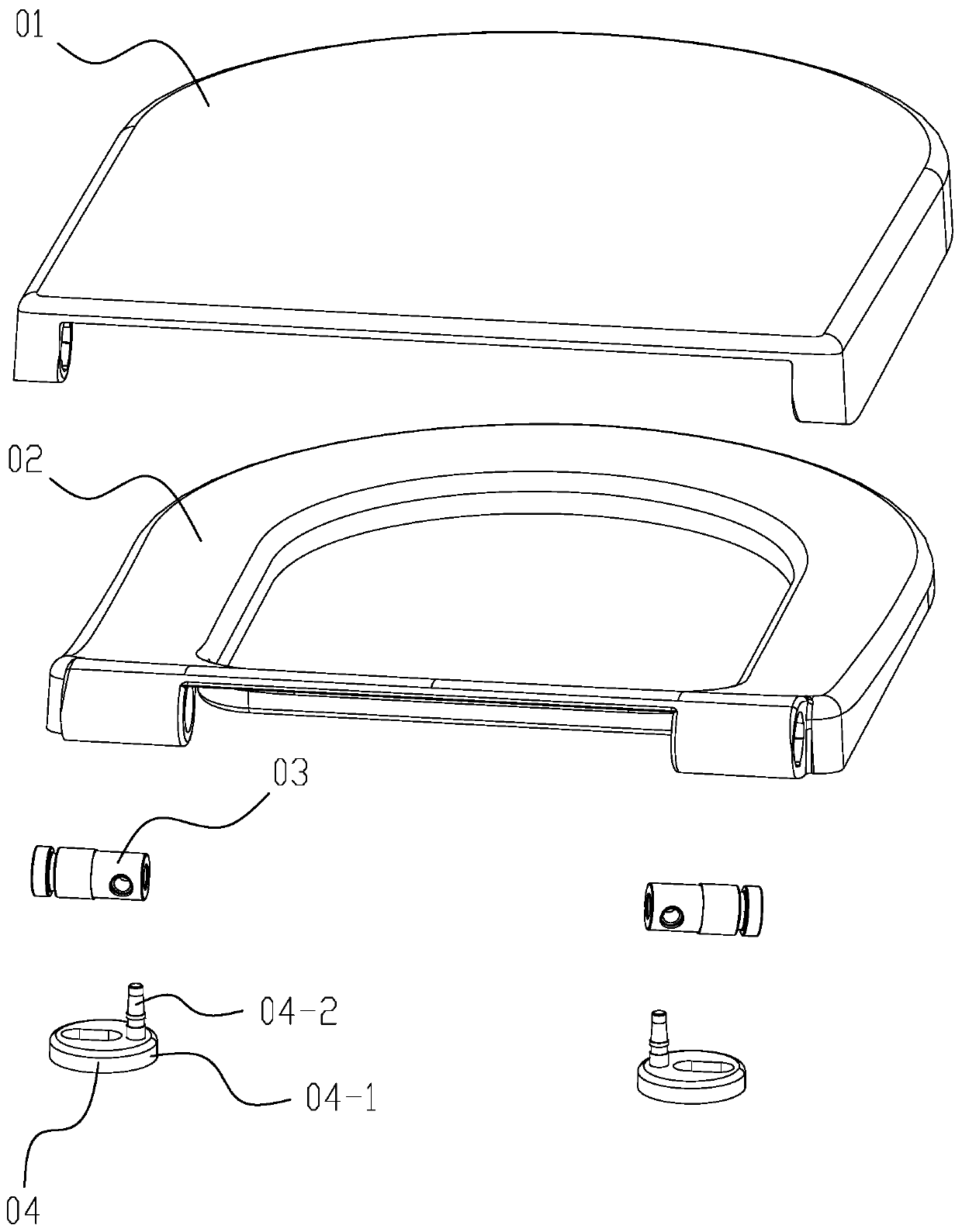
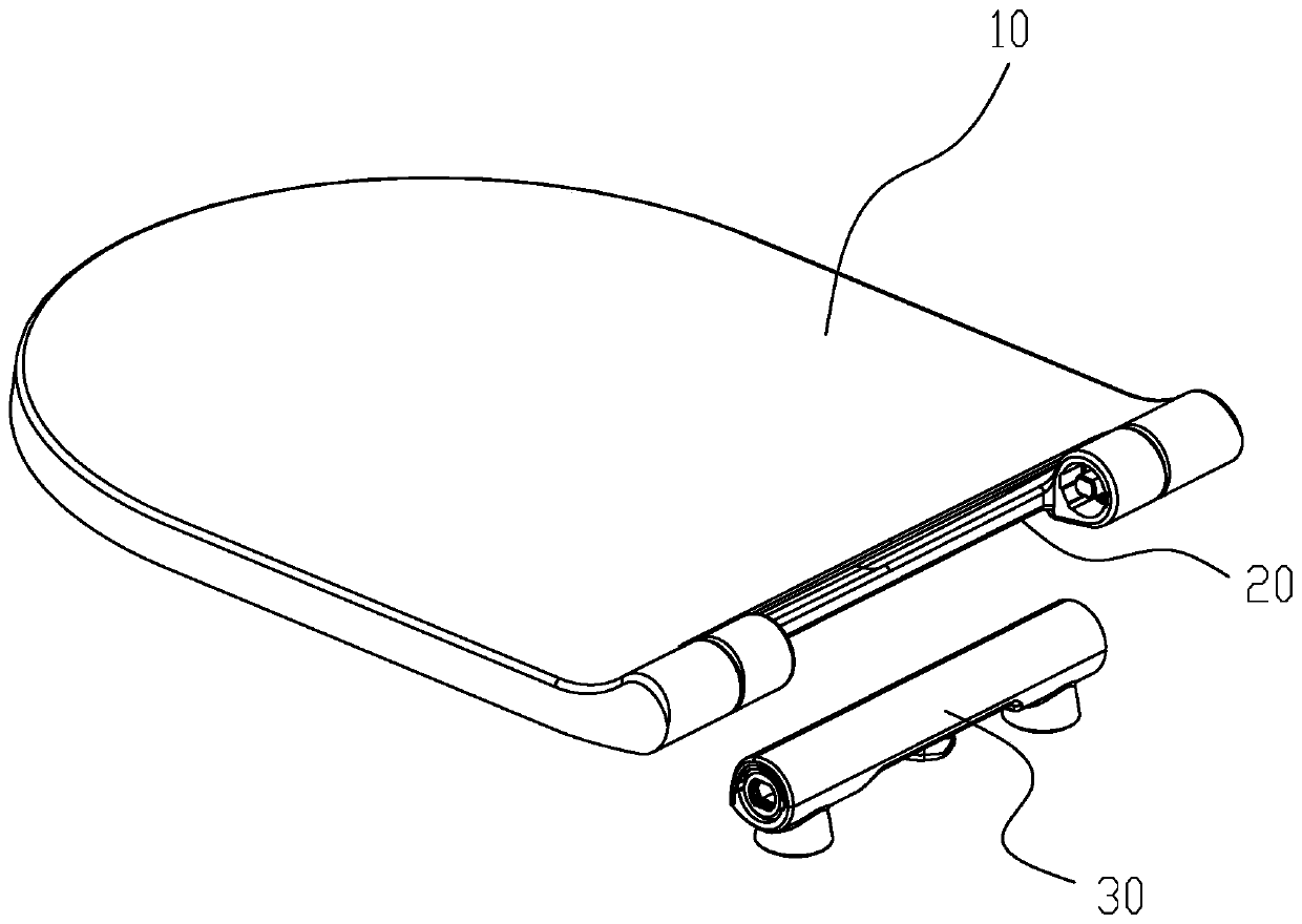
[0025] Please refer to figure 2 and image 3 , The toilet cover includes an upper cover 10 and a seat ring 20, and the connecting parts on both sides of the rear end of the upper cover are respectively rotatably connected with the connecting parts on both sides of the rear end of the seat ring. The toilet cover disassembly mechanism 30 of the present invention is used to connect the toilet cover and the toilet seat (not shown), so that the toilet cover can be quickly installed on the toilet seat, or quickly disassembled from the toilet seat down.

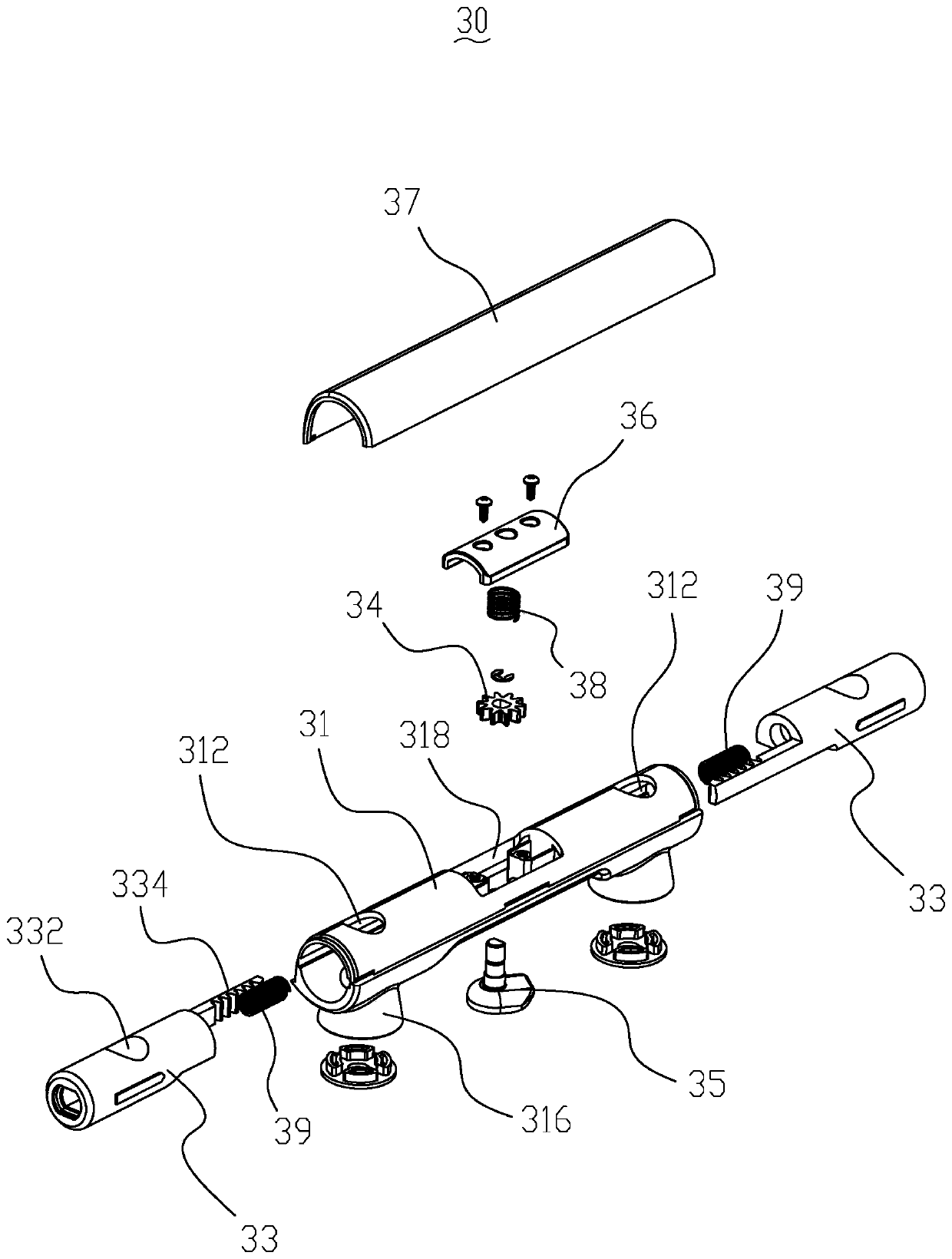
[0026] Please refer to Figure 4 and Figure 5 , the dismounting mechanism 30 includes a shaft sleeve 31, the shaft sleeve 31 is locked on the toilet seat 40 by two bolts 32, the two ends of the shaft sleeve 31 are symmetrically provided with vertically penetrating installation holes 312, the installation The hole 312 is preferably radially and vertically penetrated, so that the centerline of the mounting hole is perpendicular ...

Embodiment 2

[0038] Please refer to Figure 7 and Figure 8 , the difference between the second embodiment and the first embodiment has the following points: First, the connector 33 is not an independent component, but an assembly, including the damper 33-1 and the bushings 33-2, 33 covering the damper -1 The damper is arranged in the bushing 31, the bushing 33-2 is provided with a push-pull rod 334, and the push-pull rod 334 is axially pulled to make the connecting piece 33 move axially, if the damper 33-1 If the push-pull rod 334 is directly installed, the bushing 33-2 can be omitted; secondly, the switch 35 is covered with a drive gear 352, which is meshed with the gear 34 for transmission, and the gear 34 corresponds to the push-pull rod 334 one by one. Switch 35, drive gear 352 rotate together, drive gear 34 to rotate, make push-pull bar 334 move; During installation or disassembly, the connecting piece 33 shrinks inwards to make way for the bolt 32 , and the bolt 32 can be installe...

Embodiment 3

[0041] Please refer to Figure 9 and Figure 10 The difference between the third embodiment and the second embodiment is: first, the connecting piece 33 also includes a connecting shaft 33-3, the connecting shaft 33-3 and the damper 33-1 are axially plugged together, and the cover plate is installed and locked In this state, the end of the connecting shaft 33-3 stretches out from the sleeve 31, and the connecting shaft 33-3 is provided with a relief through hole 332 corresponding to the installation hole 312; secondly, the switch 35 drives the gear 34 to rotate, and the gear 34 drives the push-pull rod 334 to move, and the upper cover 36 covers the gear 34; thirdly, the mounting hole 312 penetrates downward through the support base 316, and the support base 316 is internally screwed with a spacer 311, and the bolt 32 passes through the spacer 311, the head of the bolt is pressed against the pad.

[0042] The connector 33 of this solution adds a connecting shaft 33-3. Since t...


PUM


Abstract

The invention discloses a closestool cover plate disassembling and assembling mechanism, and the mechanism comprises a shaft sleeve, wherein the shaft sleeve is locked on a closestool seat basin through a bolt, and vertically-through installation holes are symmetrically formed in the two ends of the shaft sleeve; the bolt penetrates through the installation holes from top to bottom to be connectedwith the closestool seat basin in a locked mode. The mechanism further comprises a connecting part which is arranged in the shaft sleeve and can do axial reciprocating motion. When the cover plate isin a detached state, the connecting part is integrally retracted into the shaft sleeve; when the cover plate is mounted, the end part of the outer side of the connecting part extends out of the shaftsleeve. The installation holes vertically penetrate through the shaft sleeve, and the shaft sleeve is locked on the toilet bowl seat basin through the bolt; compared with the mode that the shaft sleeve is connected to the cover plate, the shaft sleeve is locked and fixed on the closestool seat basin, and the shaft sleeve can be firmly locked, so the shaking of the shaft sleeve is avoided, the lateral displacement resistance of the cover plate is greatly improved, and the closestool cover plate has the advantage of being stable in structure. Besides, the cover plate can be rapidly disassembledand assembled by controlling the connecting part to stretch out and draw back, that is, the connecting part is inserted into the cover plate when stretching out in the axial direction and is separated from the cover plate when retracting in the axial direction, and the structure is simple and reliable.

Description

technical field [0001] The invention relates to a disassembly mechanism for a toilet cover assembly. Background technique [0002] Such as figure 1 As shown, the toilet cover usually includes an upper cover 01 and a seat ring 02, and the toilet cover and the toilet seat are quickly disassembled and connected through a disassembly mechanism. The disassembly mechanism generally includes a connecting shaft 03 and a support 04, and the connecting shaft 03 It is arranged in the pivot joint part of the upper cover 01 or the rear end of the seat ring 02, the support 04 is installed on the toilet seat, and the support 04 is plugged with the connecting shaft 03 to fix the upper cover 01 and the toilet seat. seat ring 02. The support 04 includes a chassis 04-1 and a latch 04-2. The chassis 04-1 is provided with a long mounting hole for locking bolts, and the latch 04-2 is arranged at an eccentric position of the chassis. [0003] Because the bolts and bolts are distributed on the c...

Claims


Application Information

Patent Timeline
Patent Type & Authority Applications(China)
IPC IPC(8): A47K13/00A47K13/26
CPCA47K13/00A47K13/26
Inventor 潘瑞雪张永浓彭东于兴义
Owner OCEANWELL XIAMEN IND CO LTD
Why Eureka
Try Eureka